12 ImagePRO-II • User’s Guide
2. Hardware Orientation
ImagePRO-II Rear Panel
rëáåÖ=cêçåí=m~åÉä=_ìííçåë
Pressing a front panel button once causes that button to light up. If the button is associated
with a menu system, the display shows the top-level menu for that button. For example,
pressing SEL at the Status Menu displays the Setup Menu. If the button performs a
function, that function begins. For example, pressing ESC exits a menu or cancels an
operation immediately.
There are three button states:
• Lit – Button is selected.
• Dim – Source or logo is present but not active.
• Not lit – Button is not selected.
fã~ÖÉmolJff=oÉ~ê=m~åÉä
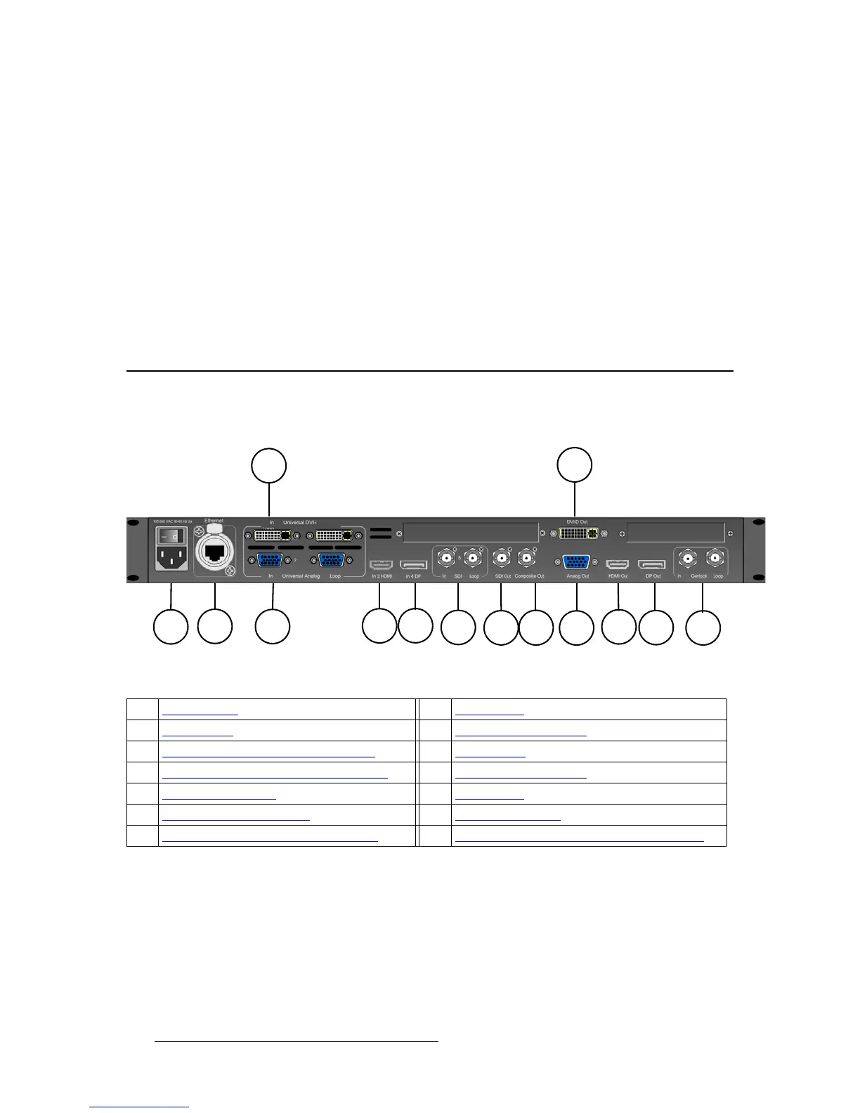
The following figure illustrates the ImagePRO-II rear panel.
Figure 2-6. ImagePRO-II Rear Panel
Following are descriptions of each rear panel connector:
1) AC Connector
One AC Connector with a power switch is provided to connect the ImagePRO-II
to your facility’s AC power source through the supplied power cord. The integral
switch turns the unit on and off.
100-240 VAC, 47-63 Hz
1) AC Connector 8) SDI-1 Output
2) Ethernet Port 9) Composite Video Output
3) Input 1 — DVI-I Input with Loop-through 10) DVI-D Output
4) Input 2 — Analog Input with Loop-through 11) Universal Analog Output
5) Input 3 — HDMI Input 12) HDMI Output
6) Input 4 — DisplayPort Input 13) DisplayPort Output
7) Input 5 — SDI-1 Input with Loop-through 14) Genlock Input BNC with passive Loop-through