16-4 9424200996
Power (32) Protection BE1-11m
Block Logic Input
The Block input provides logic-supervision control of the element. When true, the Block input disables the
element by forcing the Trip and Pickup outputs to logic 0 and resetting the element timer. Connect the
element Block input to the desired logic in BESTlogicPlus. When the element is initially selected from the
Elements view, the default condition of the Block input is a logic 0.
Logic Connections
Power element logic connections are made on the BESTlogicPlus screen in BESTCOMSPlus. The power
element logic block is illustrated in Figure 16-3. Logic inputs and outputs are summarized in Table 16-1.
Figure 16-3. Power Element Logic Block
Table 16-1. Logic Inputs and Outputs
Disables the 32 function when true
True when the 32 element is in a trip condition
True when the 32 element is in a pickup condition
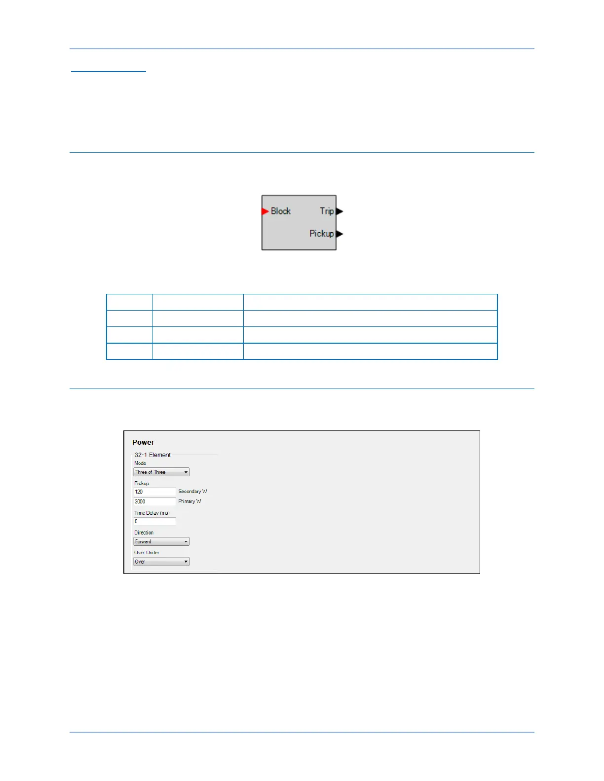
Operational Settings
Power element operational settings are configured on the Power (32) settings screen (Figure 16-4) in
BESTCOMSPlus.
Figure 16-4. Power Settings Screen