18-2 9424200996
Power Factor (55) Protection BE1-11m
If the 60FL element trip logic is true and Block Power/Power Factor is enabled, all functions that use
power measurements are blocked. See the Fuse Loss (60FL) chapter for more information on the 60FL
function.
Protective elements blocked by 60FL should be set so that trip times are 60 milliseconds or greater to
assure proper coordination of blocking.
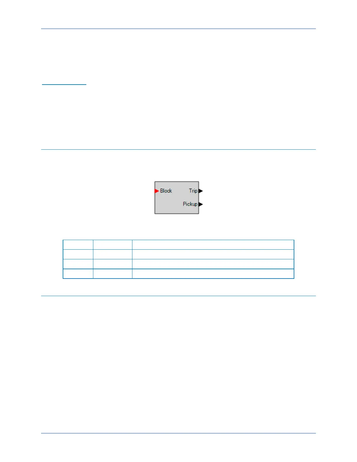
Block Logic Input
The Block input provides logic-supervision control of the element. In a typical application, the power factor
element will be blocked during motor start-up and until reaching synchronous speed.
When true, the Block input disables the element by forcing the Trip and Pickup outputs to logic 0 and
resetting the element timer. Connect the element Block input to the desired logic in BESTlogicPlus. When
the element is initially selected from the Elements view, the default condition of the Block input is a logic
0.
Logic Connections
Power factor element logic connections are made on the BESTlogicPlus screen in BESTCOMSPlus. The
power factor element logic block is illustrated in Figure 18-1. Logic inputs and outputs are summarized in
Table 18-1.
Figure 18-1. Power Factor Element Logic Block
Table 18-1. Logic Inputs and Outputs
Disables the 55 function when true
True when the 55 element is in trip condition
True when the 55 element is in pickup condition
Operational Settings
Power factor operational settings are configured on the Power Factor (55) settings screen (Figure 18-2) in
BESTCOMSPlus.