9424200996 37-5
BE1-11m Breaker Monitoring
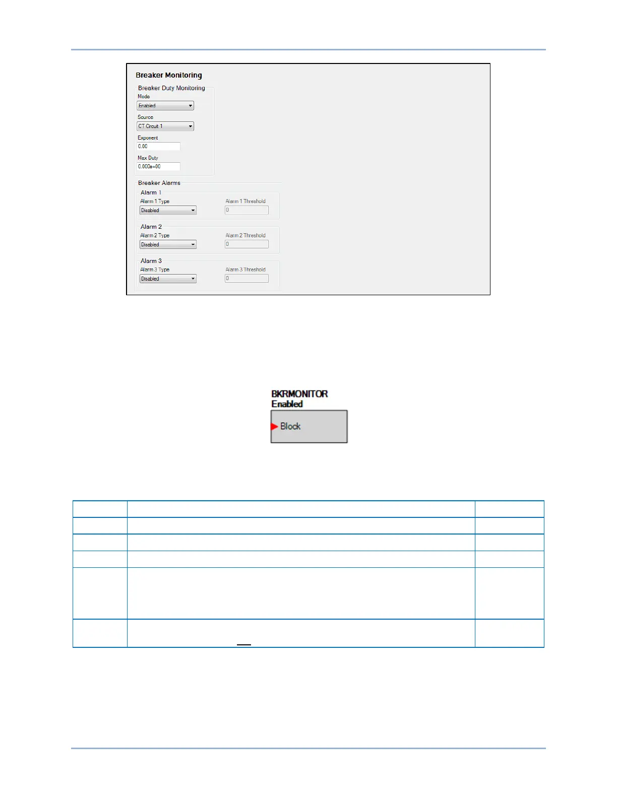
Figure 37-4. Breaker Monitoring Screen
To connect the Block logic input, use the Settings Explorer within BESTCOMSPlus to open the
BESTlogicPlus Programmable Logic tree branch and select the breaker monitor logic block from the list of
Elements. Use the drag and drop method to connect a variable or series of variables to the input. Refer to
the BESTlogicPlus chapter for more information on setting BESTlogicPlus programmable logic.
The breaker monitor logic block is shown in Figure 37-5.
Figure 37-5. Breaker Monitor Logic Block
Table 37-3 summarizes the Breaker Duty Monitoring settings.
Table 37-3. Breaker Duty Monitoring Settings
Select CT Circuit 1 or CT Circuit 2
1 to 3 in increments of 0.01
Max Duty
0 to 42,000,000 in increments of 1
The Max Duty parameter represents the maximum duty that the breaker
contacts can withstand before needing service. Max Duty is programmed in
primary amperes using exponential floating point format.
0.000e+00
Block
Logic input that blocks the breaker monitoring logic when true. When true,
breaker operations are not counted.
0
Retrieving Breaker Duty Information
BESTCOMSPlus Navigation Path: Metering Explorer, Reports, Breaker Monitor
HMI Navigation Path: Metering Explorer, Reports, Breaker Report
Breaker duty values can be read at the front-panel display. Duty values can be changed by using the
front-panel Edit key. Write access to reports is required to edit breaker duty values. Duty values can also