41-4 9424200996
Trip Circuit Monitor (52TCM) BE1-11m
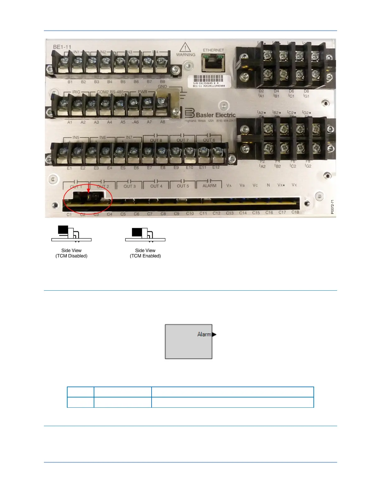
Figure 41-4. Trip Circuit Monitor Enable/Disable Jumper Location
Logic Connections
Trip circuit monitor logic connections are made on the BESTlogicPlus screen in BESTCOMSPlus. The trip
circuit monitor element logic block is illustrated in Figure 41-5. The logic output is summarized in Table
41-2.
Figure 41-5. Trip Circuit Monitor Element Logic Block
Table 41-2. Logic Output
True when voltage is not detected in the trip circuit
Operational Settings
Trip circuit monitor element operational settings are configured on the Trip Circuit Monitor (52TCM)
settings screen (Figure 41-6) in BESTCOMSPlus.