9424200996 48-5
BE1-11m BESTlogic™Plus
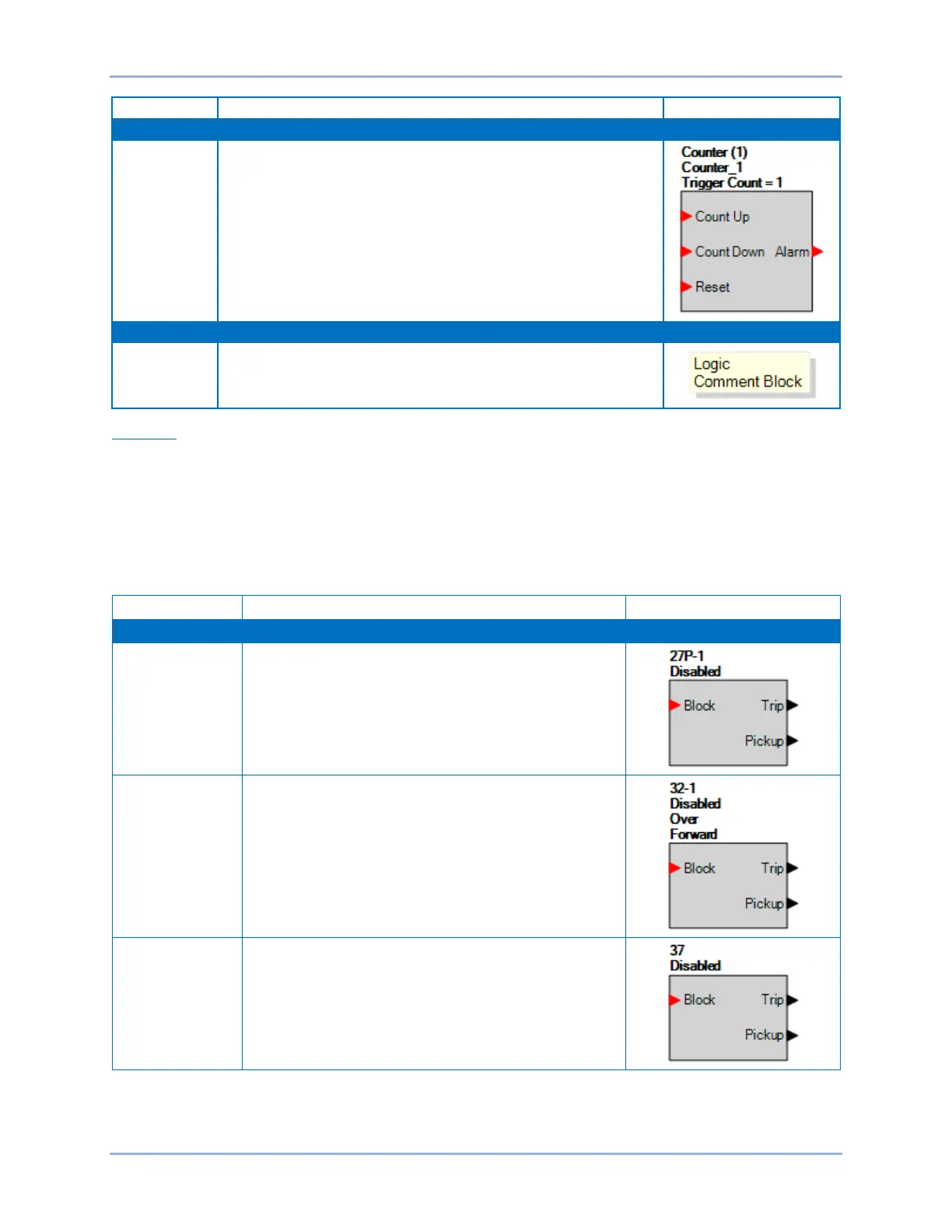
Counters
A logic counter produces a true Alarm output when the elapsed
count is greater than or equal to the Trigger Count setting after a
false to true transition occurs on the Count Up input from the
connected logic. A positive going edge on the Reset input will reset
the counter. The count will be reduced by 1 each time a false to true
transition occurs on the Count Down input. Double-click or right-click
on the logic counter to select from counters 1 through 8.
Comment
Block
The logic comment block is used to place notes on the logic.
Elements
This group contains elements for the 27P, 32, 37, 40Q, 43, 48, 49RTD, 49TC, 50, 50BF, 51, 55, 59P,
59X, 60FL, 62, 81, 86, 87, and 101. It also contains elements for 52TCM, Breaker Monitor, Breaker
Status, Fault Trigger, Email Trigger, Setting Group Control, Analog Inputs 1-8, User Programmable
Alarms 1-16, User Programmable Targets 1-12, Motor Status, Logic Labels 1-12, Indicators 1-7, Major
Alarm Reset, Minor Alarm Reset, Logic Alarm Reset, and Target Reset.
Table 48-3 lists the names and descriptions of the elements in the Elements group.
Table 48-3. Elements Group, Names and Descriptions
Phase Undervoltage Protection.
Refer to the Phase Undervoltage (27P) Protection chapter.
Refer to the Power (32) Protection chapter.
Instantaneous Undercurrent Protection.
Refer to the Instantaneous Undercurrent (37) Protection
chapter.