55-2 9424200996
Acceptance Testing BE1-11m
IRIG Verification (if used)
Purpose: To verify that the BE1-11m acquires and updates IRIG time and date information.
Step 1: Connect a suitable IRIG source to BE1-11m terminals A1 (+) and A2 (–).
Step 2: Upon receiving the IRIG signal, the BE1-11m clock will be updated with the current time, day,
and month. Verify this on the Metering > Status > Real Time Clock screen on the front-panel
display.
Contact Sensing Inputs
Purpose: To verify that the BE1-11m senses hardware input status.
Step 1: Apply an external voltage source within the range of the voltages listed in Table 55-2 to contact
sensing inputs IN1 (B1/B2), IN2 (B3/B4), IN3 (B5/B6), IN4 (B7/B8), IN5 (E1/E2), IN6 (E3/E4),
and IN7 (E5/E6).
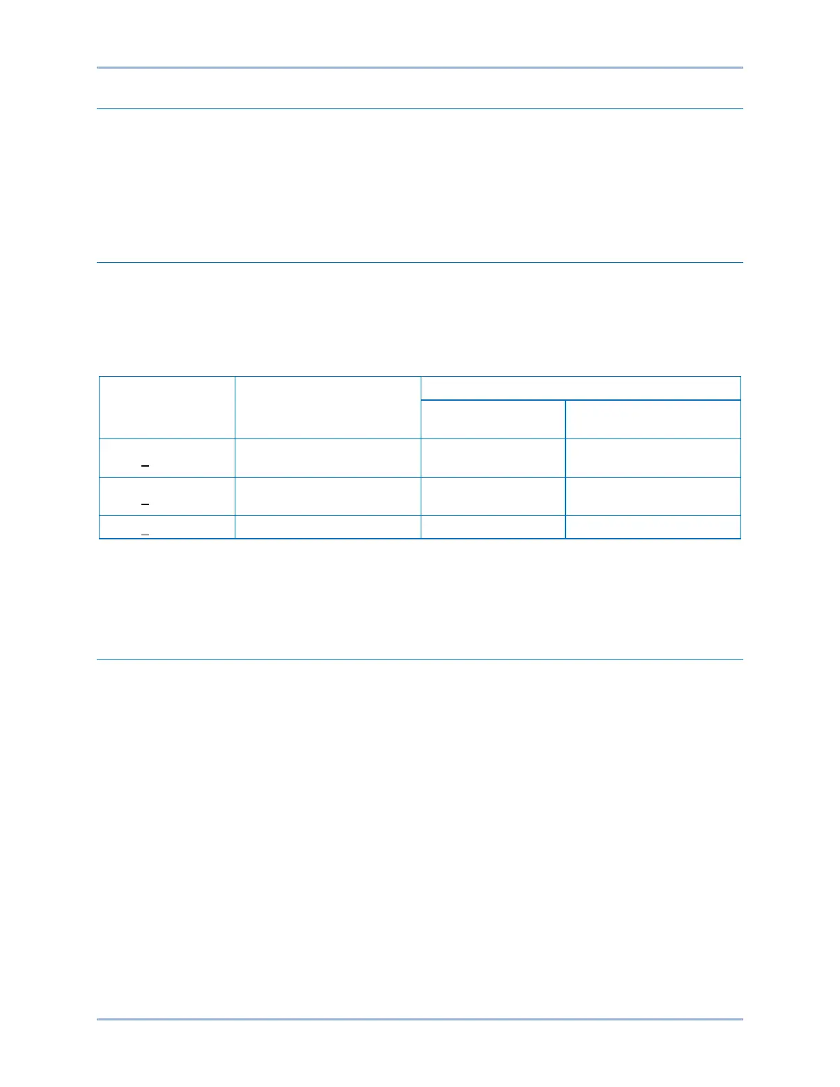
Table 55-2. Contact Sensing Turn-On Voltages
Style Option Nominal Input Voltage
Contact Sensing Turn-On Voltage*
Jumper Installed
(Low Position)
Jumper Not Installed
(High Position)
Mxx1xxxxxxxxxx 48 Vdc or 125 Vac/dc 26 to 38 Vdc
69 to 100 Vdc
56 to 97 Vac
Mxx2xxxxxxxxxx 125/250 Vac/dc
69 to 100 Vdc
56 to 97 Vac
138 to 200 Vdc
112 to 194 Vac
* For information on setting contact-sensing input jumpers, refer to the Contact Inputs and Outputs
chapter.
Step 2: To verify that all inputs have been detected, use the Metering Explorer in BESTCOMSPlus to
open the Status, Inputs screen.
Control Outputs
Purpose: To verify that the BE1-11m senses hardware output status.
Step 1: Connect to the BE1-11m through BESTCOMSPlus.
Step 2: Use the Metering Explorer to open the Control, Output Override screen.
Step 3: Click on the Disabled button for Output #1. The button changes to Enabled indicating that the
output control override capability of the relay is enabled.
Step 4: Select Set from the Action drop-down menu and click on the green arrow button to energize
Output #1. Verify that the Output #1 Status LED, located on the Output Override screen of
BESTCOMSPlus, turns on. Navigate to the Metering > Status > Outputs screen on the front-
panel display and verify that Output #1 changes state.
Step 5: Select Reset from the Action drop-down menu and click on the green arrow button to de-
energize Output #1. Verify that the Output #1 Status LED, located on the Output Override
screen of BESTCOMSPlus, turns off. Navigate to Metering > Status > Outputs on the front-
panel display and verify that Output #1 changes state.
Step 6: Verify that the sequence of events recorder logged the events by using the Metering Explorer in
BESTCOMSPlus to open the Reports, Sequence of Events screen.