60-2 9424200996
Auxiliary Overvoltage (59X) Test BE1-11m
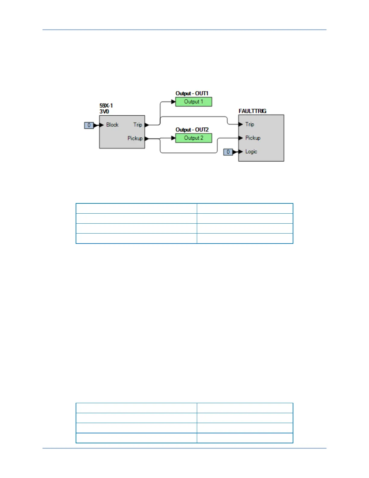
Step 2: Use BESTCOMSPlus to configure the BESTlogicPlus programmable logic shown in Figure
60-1.
• Blocking is disabled.
• OUT1 closes for 59X-1 Trip.
• OUT2 closes for 59X-1 Pickup.
• Fault recording is enabled.
Figure 60-1. BESTlogicPlus Settings (3V0 Mode)
Step 3: Use BESTCOMSPlus to open the Protection, Voltage, Overvoltage (59X-1) screen and send
the first row of test settings in Table 60-2 to the BE1-11m.
Table 60-2. Pickup Test Settings (3V0 Mode)
Step 4: Prepare to monitor the 59X-1 function operation. Operation can be verified by monitoring OUT2
(see Figure 60-1).
Step 5: Connect and apply a 150 Vac, three-phase voltage source to terminals C13 (A-phase), C14 (B-
phase), C15 (C-phase), and C16 (neutral).
Step 6: Slowly increase the A-phase voltage until OUT2 closes around 265 volts (150 Vac nominal +
115 V 3V0 pickup setting) and record the pickup. Verify that there is a 59X-1-3V0 target on the
front-panel display. Slowly decrease the A-phase voltage until OUT2 opens and record the
dropout. Reset the target.
Step 7: Verify the pickup and dropout accuracy at a pickup setting of 65 V and 20 V as listed in Table
60-2. Record the results.
Step 8: (Optional.) Repeat steps 1 through 7 for the B-phase and C-phase voltage inputs.
Step 9: (Optional.) Repeat steps 1 through 8 for settings group 1, 2, and 3.
Step 10: (Optional.) Repeat steps 1 through 9 for 59X-2.
Timing Verification (3V0 Mode)
Step 1: Use BESTCOMSPlus to open the Protection, Voltage, Overvoltage (59X-1) screen and send
the first row of test settings in Table 60-3 to the BE1-11m for settings group 0.
Table 60-3. Timing Test Settings (3V0 Mode)