9424200996 62-3
BE1-11m Instantaneous Undercurrent (37) Test
Step 2: Prepare to monitor the 37 timings. Timing accuracy is verified by measuring the elapsed time
between a sensing current change and OUT1 closing.
Step 3: Connect a current source and apply 0.55 Aac to terminals D1 and D2 (A-phase).
Step 4: Step the current down to 0.45 A. Measure the time delay and record the result.
Step 5: Repeat step 4 for the 5000 ms and 10000 ms time delay settings of Table 62-3. Record the
results.
Step 6: (Optional.) Repeat steps 1 through 5 for settings group 1, 2, and 3.
Step 7: (Optional.) Repeat steps 1 through 6 with CT Circuit 2 as the source for protection systems
equipped with two sets of CTs. In step 3, replace D1 with F1, D2 with F2, etc.
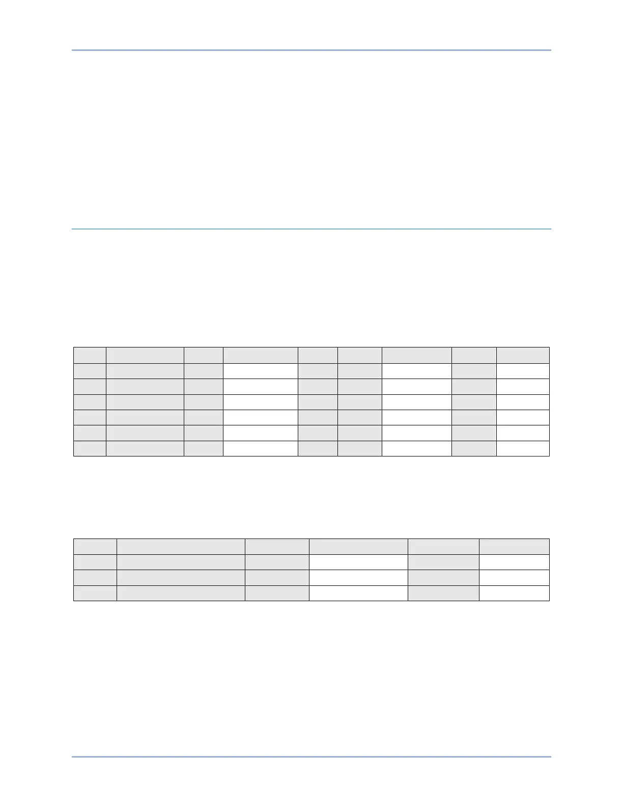
Functional Test Report
Pickup Verification
Pickup Setting Range = 0.5 to 100 A for 5A sensing
0.1 to 20 A for 1A sensing
Pickup Accuracy = ±2% or ±50 mA, whichever is greater for 5A sensing
±2% or ±10 mA, whichever is greater for 1A sensing
Dropout should occur between 101-107% of the actual pickup value.
* Dropout range is calculated from the pickup setting and may need adjusted based on actual pickup.
Timing Verification
Time Delay Range = 0 to 60000 ms
Timing Accuracy = ±0.5% or ±½ cycle, whichever is greater + 3 cycles max for currents 1.5 x pickup