62-2 9424200996
Instantaneous Undercurrent (37) Test BE1-11m
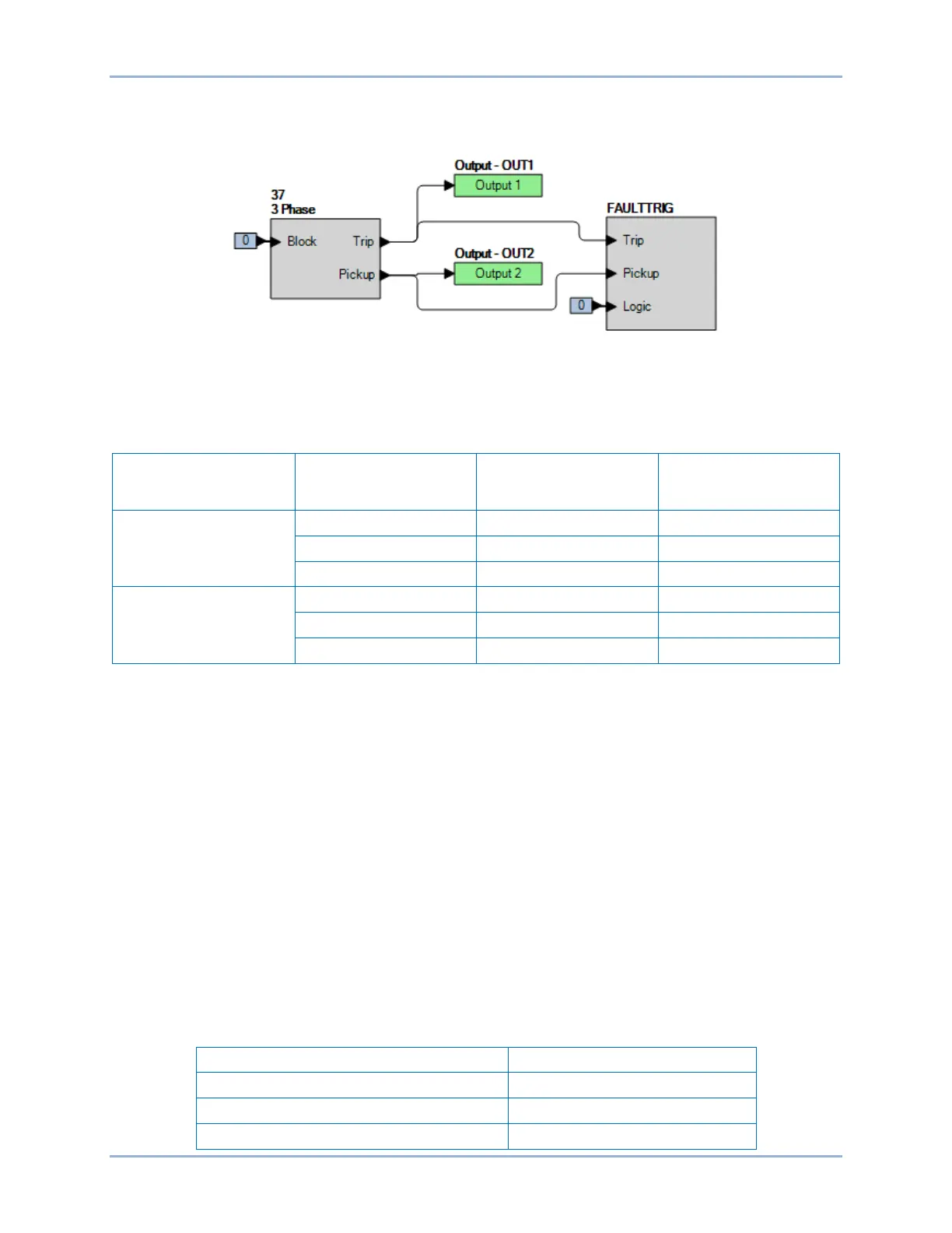
• OUT2 closes for 37 Pickup.
• Fault recording is enabled.
Figure 62-1. BESTlogicPlus Settings
Step 3: Use BESTCOMSPlus to open the Protection, Current, Instantaneous Undercurrent (37) screen
and send the low range test settings (minimum pickup setting) to the BE1-11m for your sensing
input type in Table 62-2.
Table 62-2. Pickup Test Settings
Sensing Input Type Range Pickup Setting Time Delay
5 A
1 A
Step 4: Prepare to monitor the 37 function operation. Operation can be verified by monitoring OUT2
(see Figure 62-1).
Step 5: Connect a current source and apply 0.6 Aac to terminals D1 and D2 (A-phase). Note that IA, IB,
or IC can be used for this test. Test is conducted on IA.
Step 6: Slowly decrease the A-phase current until OUT2 closes and record pickup. Verify the 37-1
target on the front-panel display. Slowly increase the applied current until OUT2 opens and
record reset.
Step 7: Repeat step 6 for the middle and high range pickup settings for your sensing input type. Record
the results.
Step 8: (Optional.) Repeat steps 1 through 7 for settings group 1, 2, and 3.
Step 9: (Optional.) Repeat steps 1 through 8 with CT Circuit 2 as the source for protection systems
equipped with two sets of CTs. In step 5, replace D1 with F1, D2 with F2, etc.
Timing Verification
Step 1: Use BESTCOMSPlus to open the Protection, Current, Instantaneous Undercurrent (37) screen
and send the first row of test settings in Table 62-3 to the BE1-11m for settings group 0.
Table 62-3. Timing Test Settings