65-4 9424200996
Inverse Overcurrent (51) Test BE1-11m
Table 65-5. Operational Settings (3I0 Mode)
System Parameters, Sensing
Transformers
Protection, Current, Inverse Overcurrent
(51-1)
Enables 51-1 function for
3I0 mode
Protection, Current, Instantaneous
Overcurrent (51-1)
Selects CT circuit 1 as the
source
Target Configuration, Targets
Enables residual target for
51-1
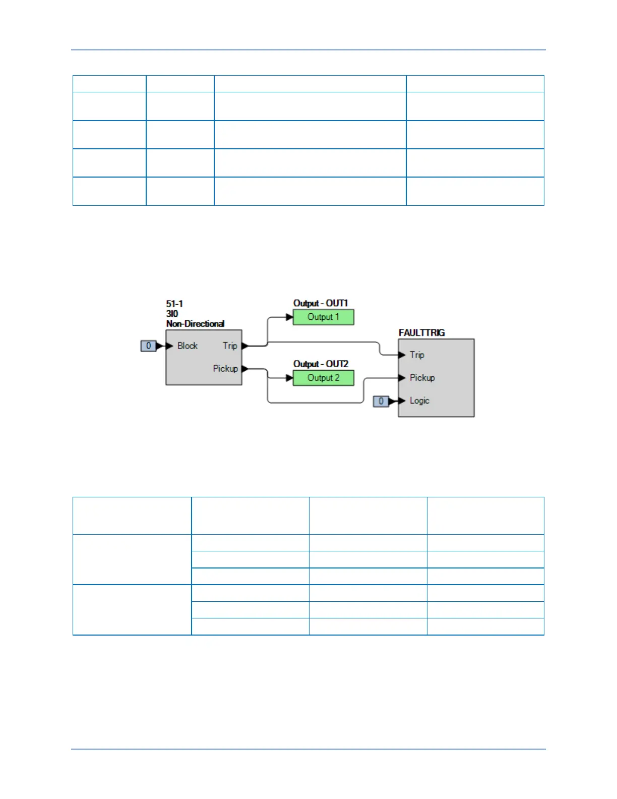
Step 2: Use BESTCOMSPlus to configure the BESTlogicPlus programmable logic shown in Figure
65-2.
• Blocking is disabled.
• OUT1 closes for 51-1 Trip.
• OUT2 closes for 51-1 Pickup.
• Fault recording is enabled.
Figure 65-2. BESTlogicPlus Settings (3I0 Mode)
Step 3: Use BESTCOMSPlus to open the Protection, Current, Inverse Overcurrent (51-1) screen and
send the low range test settings (minimum pickup setting) to the BE1-11m for your sensing input
type in Table 65-6.
Table 65-6. Pickup Test Settings (3I0 Mode)
Sensing Input Type Range Pickup Setting Time Dial
5 A
1 A
Step 4: Prepare to monitor the 51-1 function operation. Operation can be verified by monitoring OUT2
(see Figure 65-2).
Step 5: Connect a current source to terminals D1 and D2 (A-phase).
Step 6: Slowly increase the A-phase current until OUT2 closes and record the pickup. Verify that there
is a 51-1-Residual target on the front-panel display. Slowly decrease the applied current until
OUT2 opens and record the dropout.