67-2 9424200996
Power (32) Test BE1-11m
Target Configuration,
Targets
Enables phase A over target for 32-1
Target Configuration,
Targets
Enables phase A under target for 32-1
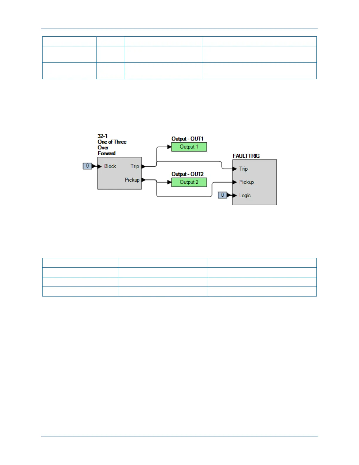
Step 2: Use BESTCOMSPlus to configure the BESTlogicPlus Programmable Logic shown in Figure
67-1.
• Blocking is disabled.
• OUT1 closes for 32-1 Trip.
• OUT2 closes for 32-1 Pickup.
• Fault recording is enabled.
Figure 67-1. BESTlogicPlus Settings
Forward Tripping Direction (Overpower)
Step 1: Using Table 67-2 as a guide, send the 32-1 settings to the BE1-11m. Prior to each directional
test, reset the BE1-11m targets from the previous test.
Table 67-2. Forward-Overpower Test Settings
Step 2: Connect and apply a 100 Vac, three-phase voltage source at nominal frequency to terminals
C13 (A-phase), C14 (B-phase), C15 (C-phase), and C16 (neutral). Connect a variable ac
current source to terminals D1 (A-phase polarity) and D2 (A-phase non-polarity).
Step 3: Set A-phase current in phase with the voltage and slowly increase the current from 0 amps until
OUT2 closes and record the pickup. Verify that there is a 32-1-A-Over target on the front-panel
display. Decrease A-phase current until OUT2 opens and record the dropout. Pickup will occur
within ±3% of the three-phase 32-1 pickup setting (500 watts = 5 amps, 100 volts, 0 degrees lag
E). See the Power (32) Protection chapter for details on single phase and total power operation.
Step 4: With the BE1-11m picked up (OUT2 closed), change the angle of the applied current to lag the
voltage by 180 degrees and verify that OUT2 opens. This verifies that the 32-1 function is
operating in the forward trip direction and not in the reverse direction.
Step 5: Repeat steps 1 through 4 for the 1,000 W and 2,000 W pickup settings in Table 67-2. Record
the results.
Step 6: (Optional.) Repeat steps 1 through 5 for B-phase and C-phase currents. (Consult the Power
(32) Protection chapter for operating details).
Step 7: (Optional.) Repeat steps 1 through 6 for settings group 1, 2, and 3.