9424200996 83-15
BE1-11m RTD Module
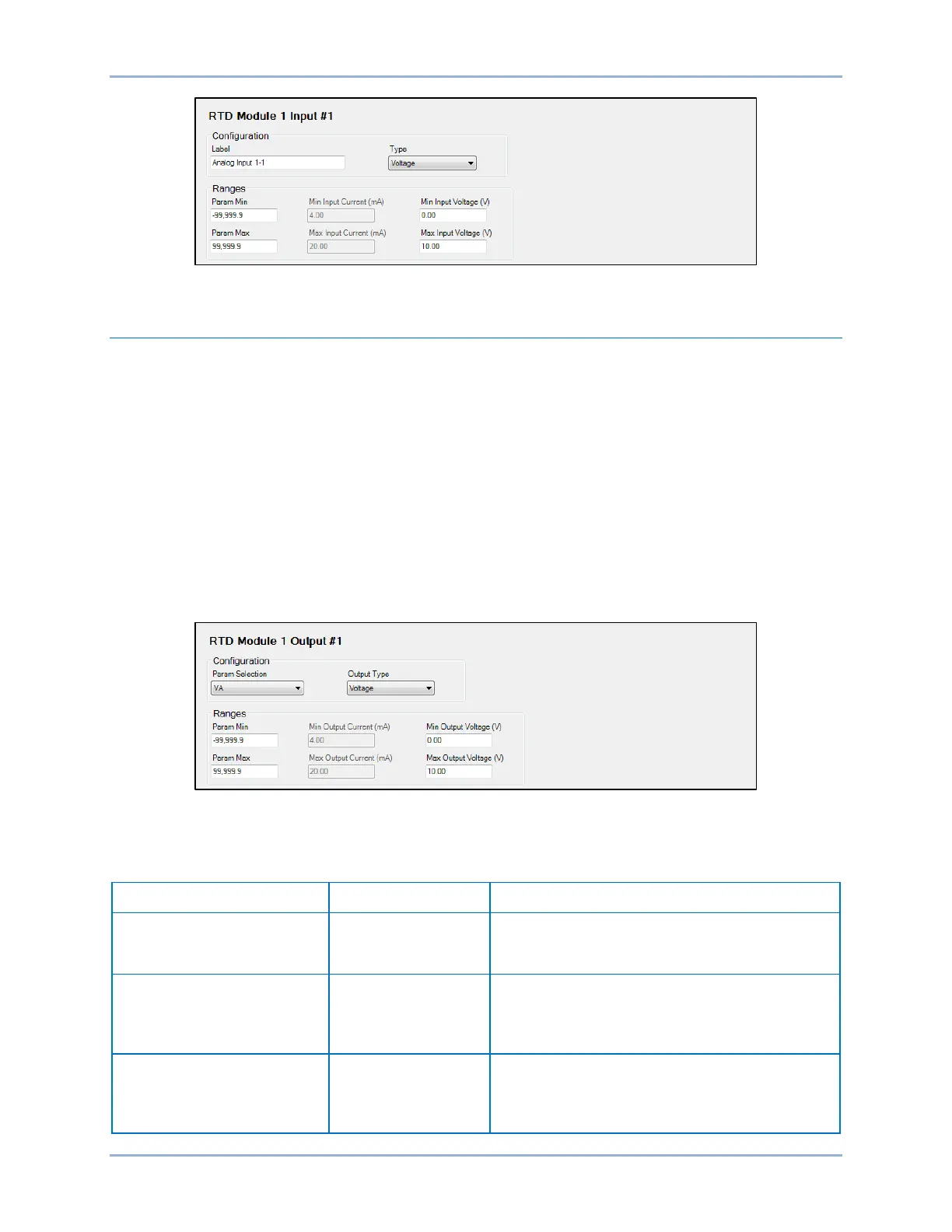
Figure 83-21. Module 1 Input #1 Screen
Remote Analog Outputs Configuration
The RTD module provides four analog outputs. The BE1-11m supports two RTD modules at once.
Configuration Settings
BESTCOMSPlus Navigation Path: Settings Explorer, Programmable Outputs, Remote Analog Outputs
HMI Navigation Path: Settings Explorer, Analog Outputs
Configuration settings are made using the BE1-11 plugin for BESTCOMSPlus. To program the
configuration settings, use the Settings Explorer to open the Programmable Outputs, Remote Analog
Outputs tree branch and select the module and output to be modified. Refer to Figure 83-22. Use the
drop-down menu under Param Selection to select a parameter. Select the Output Type. The analog
outputs are always monitored and their status is displayed on the appropriate metering screens.
Ranges must be set for the selected output type. Param Min correlates to Min Output Current or Min
Output Voltage and Param Max correlates to Max Output Current or Max Output Voltage.
Figure 83-22. Module 1 Output #1 Screen
Table 83-4 defines the units of selectable parameters.
Table 83-4. Units of Selectable Parameters
VCA, 3V0, V1, V2, Vx, Vx
rd
IA Circuit 1, IB Circuit 1, IC
Circuit 1, 3I0 Circuit 1, I1
Circuit 1, I2 Circuit 1, IG
IA Circuit 2, IB Circuit 2, IC
Circuit 2, 3I0 Circuit 2, I1
Circuit 2, I2 Circuit 2, IG