Connection diagram
Compact manual b maXX
®
BM4400, BM4600, BM4700
Document no.: 5.06014.02 Baumüller Nürnberg GmbH
22
of 94
5.1
* is only valid for BM444X, BM445X and BM446X accordingly the cooling versions S and A.
for BM447X cooling type -A:
Figure 8: Connection fan BM447X-A
** The power supply at X100 or X101 must be fused external. At the selection of the fuse you
must consider the cross-section of the connecting cable and the maximum allowable load
capacity.
In case you consider UL 508 C, you must limit the power supply to 100 W or fuse it with a UL-
listed 4 A fuse.
Ba- ... 1D1 Connections for chopper resistor and DC link, see ZFigure 9– on page 23 and the following.
R
B
Chopper resistor
PE....1W1 Mains connection, see ZFigure 9– on page 23 ff.
S1 Fuses (circuit cable + device)
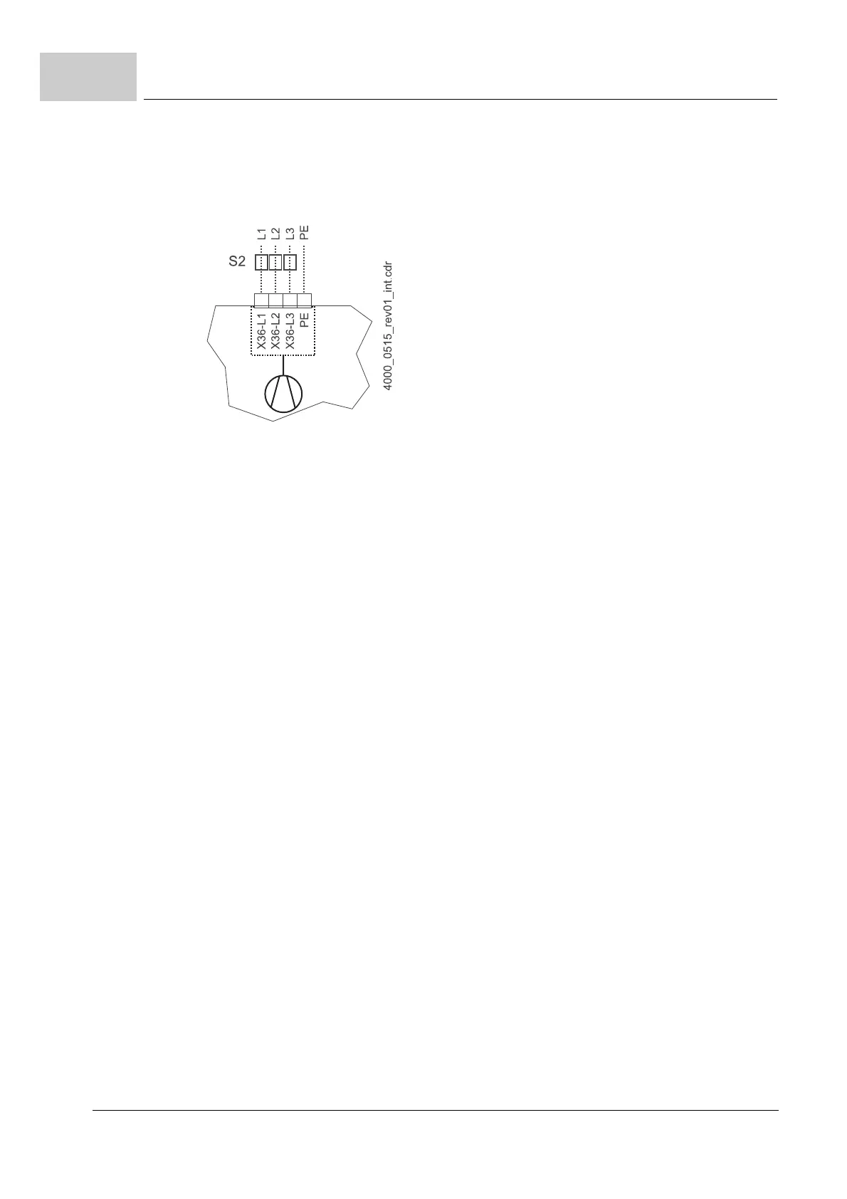
S2 Fuse (fan) *)
L1 Mains choke (not necessary for BM441X and BM442X except BM4426)
L2 Mains filter
X1 Serial interface (RS 232), see ZFigure 18– on page 32.
X3 Connections for ready-for-use, quickstop, pulse enable, see ZFigure 18– on page 32.
X36 Connections for fan (only BM444X-S/-A, BM445X-S/-A, BM446X-S/-A, BM447X-A)
X100 Connections for 24 power supply, further information see ZFigure 18– on page 32 (SELV/
PELV)
X101 Connections for brake, motor temperature, see ZFigure 9– on page 23 and the following
(SELV/PELV)
X102 Connections of the safety relay, see ZFigure 9– on page 23 and the following (SELV/PELV)
X103 Connections of the optional, second safety relay (only BM443X - BM447X)
A:X1 Encoder module, see manual 5.01042 (SELV/PELV)
ENC Encoder
BRE Brake
PE....1W2 Connections for motor, see ZFigure 9– on page 23 ff.
 Loading...


