Connection diagrams
Compact manual b maXX
®
BM4400, BM4600, BM4700
Document no.: 5.06014.02 Baumüller Nürnberg GmbH
32
of 94
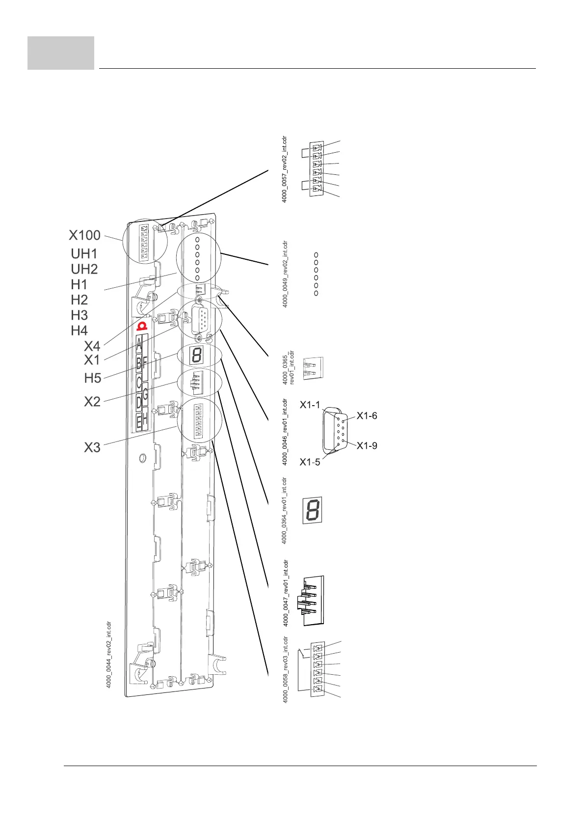
5.2
Figure 18: Connection X100 and connections of the controller unit
X100-2: +24V (SELV/PELV)
X100-3: Mains on (bus) (SELV/PELV)
X100-4: Chopper resistor (SELV/PELV)
X100-5:
M24 V (SELV/PELV)
X100-6: M24V (SELV/PELV)
UH1:green: Programmable LED
yellow: Programmable LED
UH2:green: Programmable LED
yellow: Programmable LED
H1: green: Torque direction1
yellow: Torque direction2
H2: green: Enable
yellow: Power ON
H3: red: Current limit reached
H4: red: Error
X4: reserved
6: DTR, DSR
7: RTS
8: CTS
9: reserved
1: reserved
2: TxD RS232
3: RxD RS232
4: DTR, DSR
5: Grounding
H5 Display
7 segment display
Standard operation: Display drive status
Error condition: Display error number
X2:
Connection for
Baumüller memory module PSI
X3-1: BB on (NO) (SELV/PELV)
X3-2: BB on (middle selector switch)
X3-3: Reference potential for 4 and 5
X3-4: Quickstop (SELV/PELV)
X3-5: Pulse enable (SELV/PELV)
X3-6: BB on (NC) (SELV/PELV)
 Loading...


