Connection diagrams
Compact manual b maXX
®
BM4400, BM4600, BM4700
Document no.: 5.06014.02 Baumüller Nürnberg GmbH
28
of 94
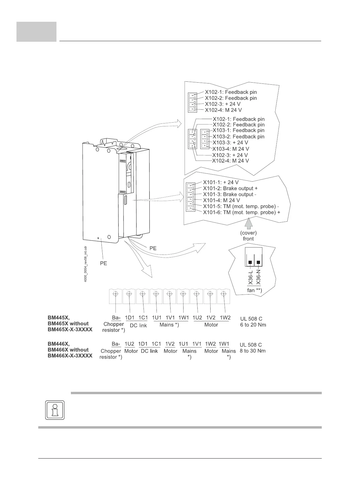
5.2
The electrical connections for the devices BM445X, BM465X, BM446X and BM466X are
shown in the following figure:
Figure 14: Electrical connections for mains, motor, upon others for BM445X, BM465X,BM446X and BM466X
*) only BM445X-S/-A and BM446X-S/-A
NOTE
The chopper resistor is connected at the devices BM445X and BM446X between Ba- and 1C1.
Also see ZFigure 6– on page 20.
 Loading...


