page17
7.6HeatingPlantEmissionsRate(HPER)
1.ToenablethehouseholdertoclaimtheFeedintariff(FIT)theheatingplantemissionratemustbecalculatedandenteredintotheMCScertificationsubmissionand
recordedintheMicrochpsystemcommissioningchecklistbenchmarksheetsatthebackoftheseinstructions.
SeetheBaxiwebsitetocalculatetheHPERvalues
http://www.baxi.co.uk/products/getfitwithbaxiecogen.htm.
Calculateperformhttp://www.ecogen.baxi.co.uk/mcsperform
2.TofindtheHeatingPlantEmissionsRatesforPlantSizeRatiosbetween0.5and4.0pleaseseethetablebelow.
PSR HPER
0.5 0.295
0.6 0.282
0.7 0.269
0.8 0.256
0.9 0.243
1 0.231
1.1 0.225
1.2 0.219
1.3 0.213
1.4 0.207
1.5to4 0.201
7.7ElectricalConnectionGeneral
1.TheproductmustbeinstalledbyacompetenttrainedelectricianthathasbeenonaBaxiapprovedcourse.
2.Thefuseratingofthesecurableisolatorshallbe13A.
3.Amainssupplyof230V~50Hzisrequired.
4.MainswiringexternaltotheproductmustbeinaccordancewiththecurrentIEE(BS7671)RequirementsforElectricalInstallation(WiringRegulations)andanylocal
regulations.
5.Connectionmustbemadeinawaythatallowscompleteisolationoftheelectricitysupplyadoublepoleswitchservingonlytheproductandsystemcontrols.Themanual
isolationswitchshallbecapableofbeingsecuredintheoff(isolation)position;thisswitchistobelocatedinanaccessiblepositionwithinthecustomer'sinstallation.
6.ConnectiontothemainsmustbemadeinaccordancewiththelatestadditionoftheEngineeringRecommendationG83RecommendationsfortheconnectionofSmall
ScaleEmbeddedGenerators(SSEG)inparallelwithpubliclowvoltagedistributionnetworks.
7.TheDistributionNetworkOperator(DNO)mustbeprovidedwithinformationregardingtheSSEGGuidanceNotes,installationonthedayofcommissioning.Anotification
sheetisprovidedwhichshouldbecompletedandsenttoyourDistributionNetworkOperator(DNO)alternativelythismaybedonethroughtheDNO'swebsite.
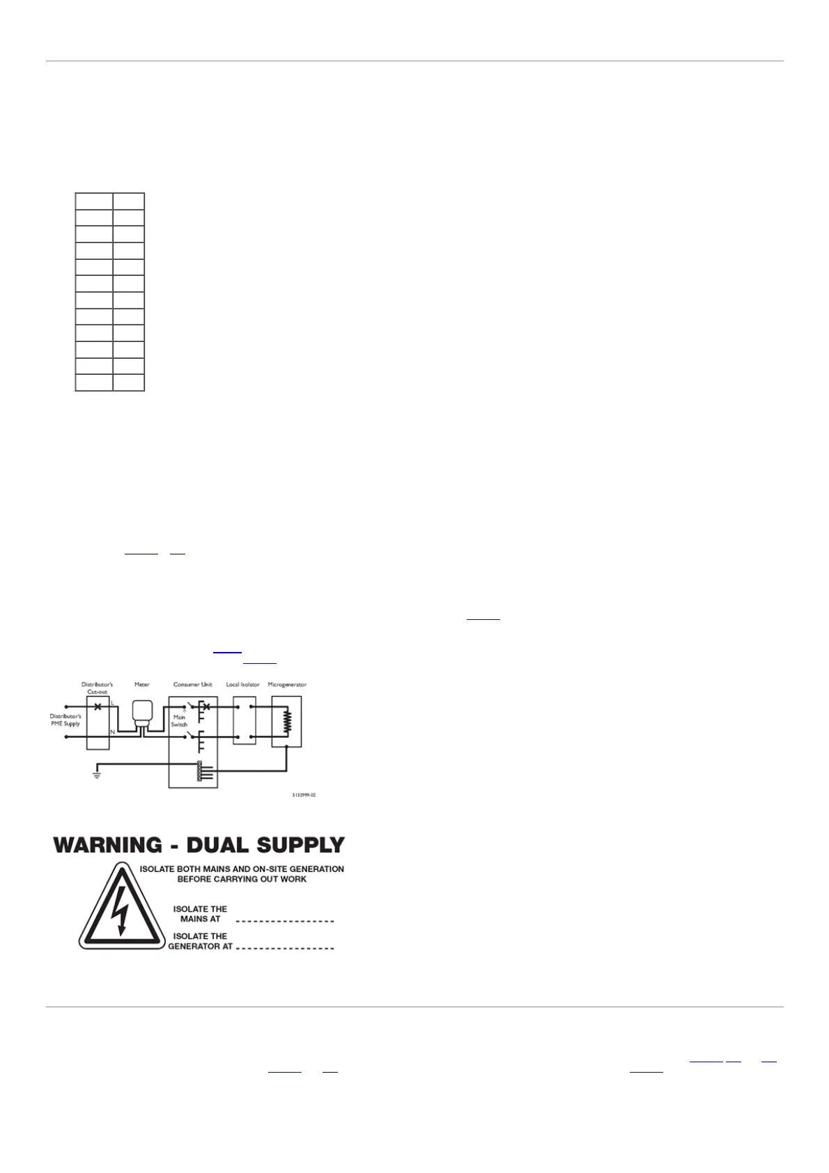
8.Twolabels(Figs.12&12a)areprovidedtobeplacedat:
a)Theconsumerunit
b)Theappliance
9.Theinstallershallprovidelabelingatthesupplyterminals(fusedcutout).meterposition,consumerunitandatallpointsofisolationwithintheuserspremisestoindicate
thepresenceofamicroCHPunit.Anexampleofthewarninglabeltobeleftonsiteisshown(Fig.12a).
10.TherearetwowaysinwhichtheEcogen24/1.0appliancecanbeelectricallyinstalled.
Connectionbydedicatedcircuit(Fig.13)
Connectionintoanexistingfinalcircuit(Fig.13a)
Fig.12
Fig.12a
page18
7.7Installerinformation
11.Whicheverofthetwooptionsischosen,itisimperativethatthesafetyoftheelectricalinstallationisnotimpairedbytheinstallationoftheEcogen24/1.0.
12.ToenabletheFITtobeclaimedtheelectricitygeneratedandexportedmustbemonitoredbymetersinstalledintotheelectricitysupplyasshowninFigs.13,13aand13b,
fortheexporteitherbidirectionalmetersasinFigs.13and13a,orbyleavingtheexistingmeterandaddinganadditionalmeterasinFig.13b.Anextrametermustbe
addedjustbeforetheappliancetomeasuretheelectricalgeneration.TheserialnumbermustbesubmittedforMCSsubmissionandrecordedinboththeDNOleafletand
theMicroCHPsystemcommissioningchecklistbenchmarksheetsatthebackoftheseinstructions.
13.TheEcogen24/1.0mustnotbeconnectedtoaninstallationbymeansofaplugandsocket.
14.Theessentialcriteriawhichmustbemetaregivenbelowforbothoptions.
15.ConnectionofanEcogentoadedicatedcircuit

 Loading...