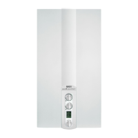
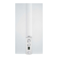
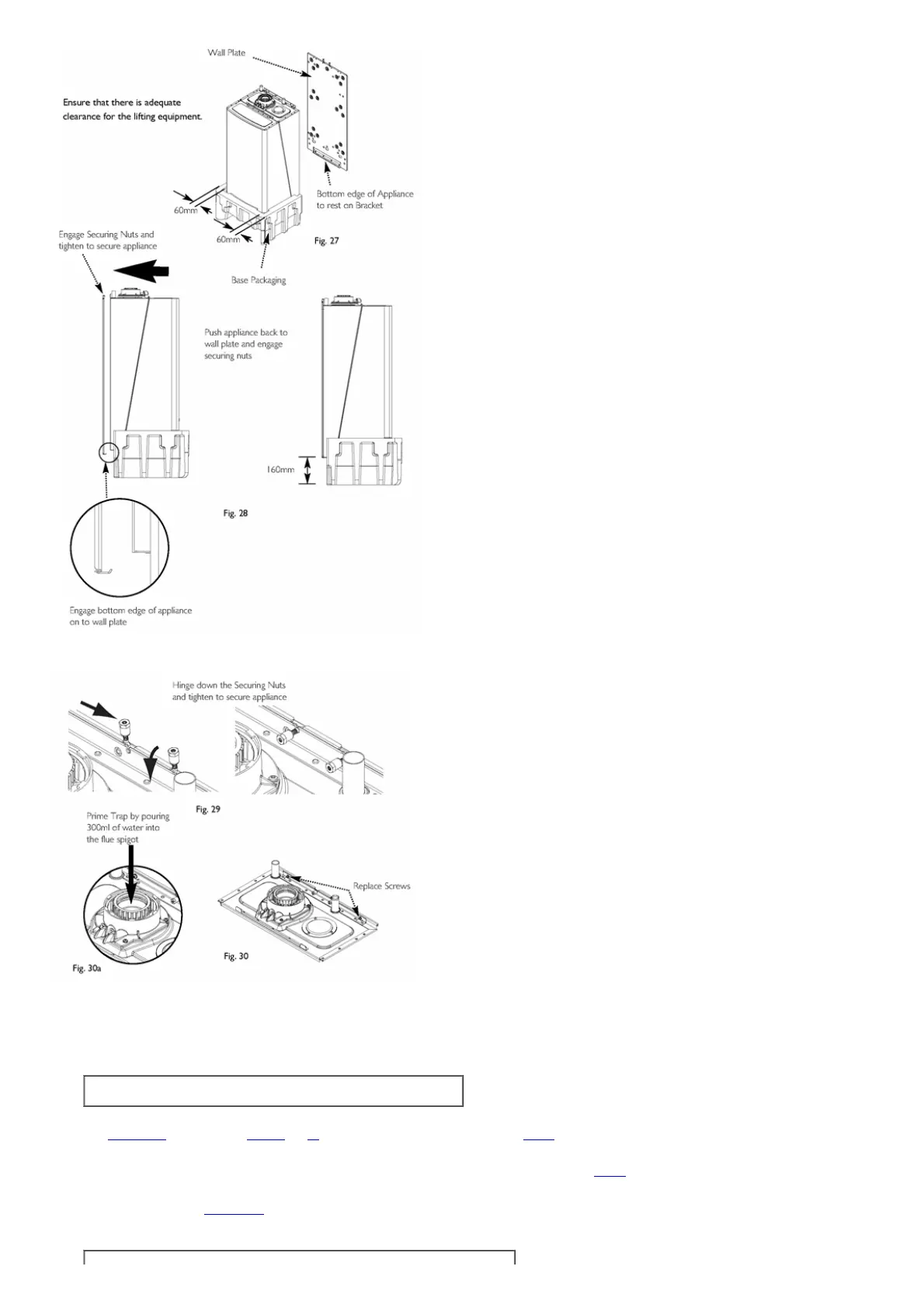
Fig.27&Fig.28
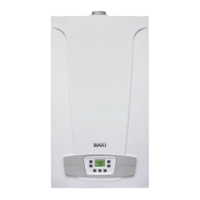
Fig.29,Fig.30&Fig.30a
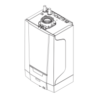
9.3Serviceconnections
1.Connectthecentralheatingcircuittothetopoftheapplianceusing22mmcompressionfittingstoavoidheatdamagetothecaseandseals;thereturnisontheleftand
theflowisontheright.
NOTE:Toassistwiththepurgingofairfromthesystempourwaterintotheflow
andreturnconnectionstodisplacetheairintheheatexchangers.
2.Connectthegastothebottomrightoftheapplianceusingthe15mmgascockprovided(inthetopofthepackaging).Removethebottomcoverandlowerthecontroltray
(SeeSection10.1paragraph3andFigs.40and41).Installwiththetestnippletotheleft(seeFig.11)thisallowstheconnectiontotheappliancetobetightnesstested
independentlyofthegaspipeworkuptotheappliancewhichthencanbetestedusingthetestnippleonthegasmeter.Itmaybedifficulttoreassemblethebottompanelif
thisisnotdone.
3.Note:Caremustbetakentoensurethattheovercurrentswitchisnotdisturbedfromitscorrectposition(SeeFig.2awhenreplacingthebottomcover).Theswitchshould
beupatthebackthe'1'shouldbedepressed.
9.4CondensateDrainseesection7.8
1.Connectthecondensatedraintothetrapoutletpipe.

 Loading...