Ensurethedischargeofcondensatecomplieswithanynationalorlocalregulationsinforce
(seeBritishGas"GuidanceNotesfortheInstallationofDomesticGasCondensingBoilers".
2.Theconnectionwillaccept21.5mm(3/4in)plasticoverflowpipewhichshouldgenerallydischargeinternallyintothehouseholddrainagesystem.Ifthisisnotpossible,
dischargeintoanoutsidedrainisacceptable.
3.Thecondensatetrapshouldbeprimedbypouringapproximately300mlofwaterintothefluespigot.Donotallowanywatertofallintotheairinlet.
page34
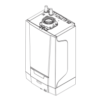
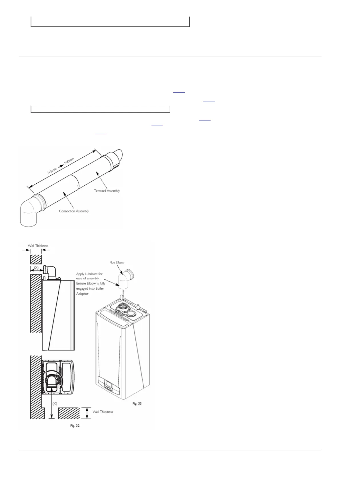
9.5FittingTheFlue
HORIZONTALTELESCOPICFLUE
1.Therearetwotelescopicsections,theTerminalAssemblyandtheConnectionAssembly,arollofsealingtapeandtwoselftappingscrews.A93°elbowisalsosupplied.
TheouterductoftheConnectionAssemblyispaintedwhite.OntheTerminalAssemblytheouterductisunpainted.
2.Thetwosectionscanbeadjustedtoprovidealengthbetween315mmand500mm(Fig.31)whenmeasuredfromtheflueelbow(thereis50mmengagementintothe
elbow).
3.Locatetheflueelbowontheadaptoratthetopoftheboiler.Settheelbowtotherequiredorientation(Fig.33).
NOTE:Theflueelbowisangledat93degreestoensureafallbacktotheboiler.
4.Measurethedistancefromtheoutsidewallfacetotheelbow.Thisdimensionwillbeknownas'X'(Fig.32).
5.Ifthedistancefromtheflueelbowtotheoutsidefaceofthewall('X'inFig.32)islessthan250mmtheConnectionAssemblycanbediscardedandtheTerminal
Assemblycutandfitteddirectlyintotheelbow.
6.Ininstanceswherethedimension'X'(Fig.32)isbetween250mmand315mmitwillbenecessarytoshortentheTerminalAssemblybycarefulcuttingtoaccommodate
wallsofthesethicknesses.
7.Todimension'X'add50mm.Thisdimensiontobeknownas'Y'.
Fig.31
Fig.32&Fig.33
page35

 Loading...