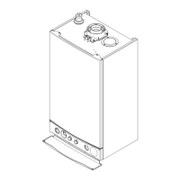
Fig.34&Fig.35
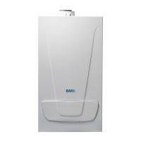
Fig.36&Fig.37
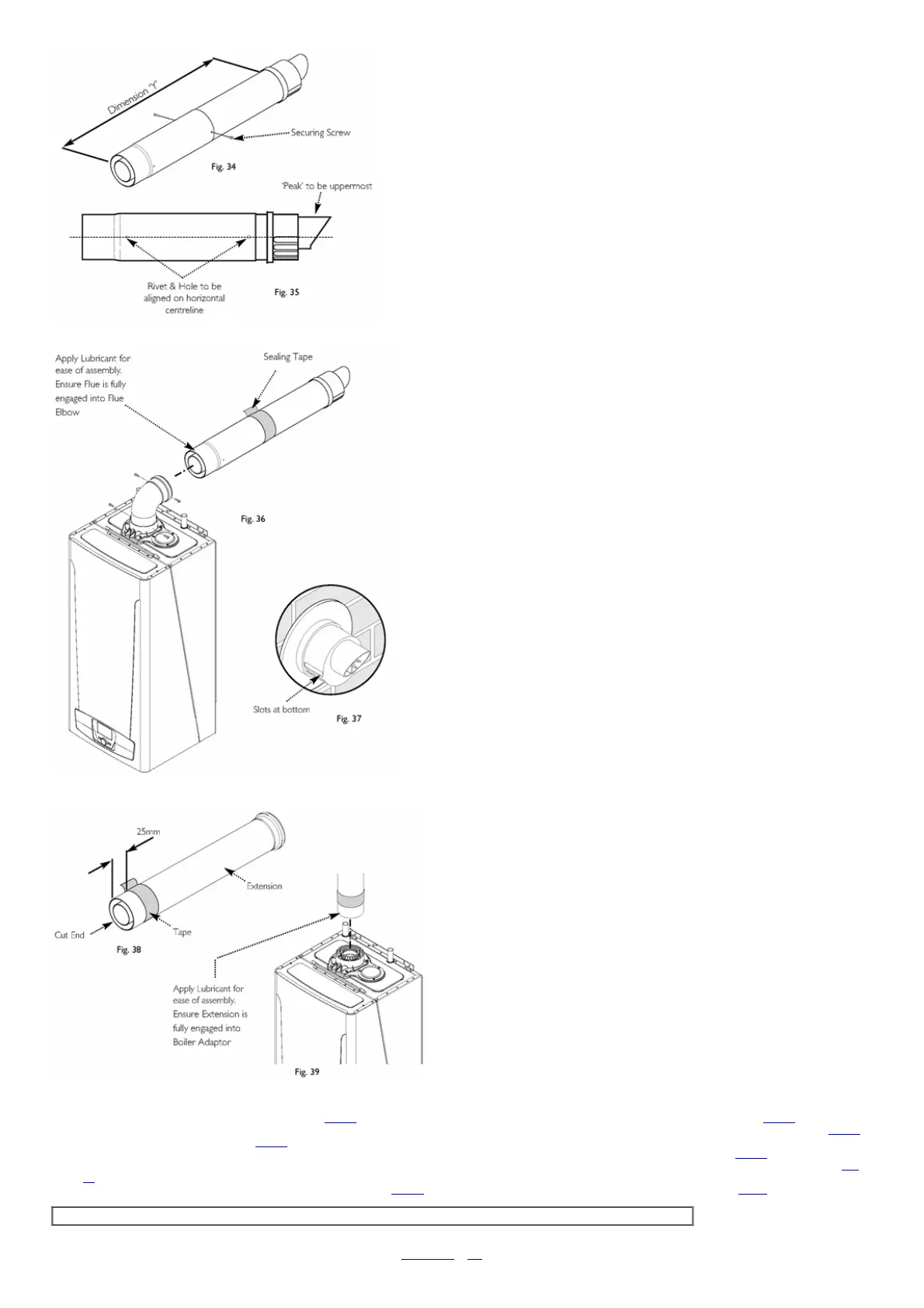
Fig.38&Fig.39
8.Adjustthetwotelescopicsectionstodimension'Y'(Fig.34).EnsurethattherivetsandholesintheConnectionAssemblyarealignedhorizontally(Fig.35).
9.Usinga2mmbit,drillthroughtheholesattheendoftheConnectionAssemblyintotheTerminalAssemblyandsecurethemtogetherusingthescrewssupplied(Fig.34).
Sealthejointwiththetapeprovided(Fig.36).
10.Removetheflueelbowandinsertthefluethroughtheholeinthewall.Refittheelbowtotheboileradaptor,ensuringthatitispushedfullyin(Fig.36).
11.Drawthefluebackthroughthewallandengageitintheelbow.Itmaybenecessarytousesoapsolutionorsimilartoeaseassemblyoftheelbowadaptorandflue(Fig.
36).
12.Ensurethattheterminalispositionedwiththeslotstothebottom(Fig.37).Securethefluetotheelbowwiththeselfdrillingscrewssupplied(Fig.36).
IMPORTANT:Itisessentialthattheflueterminalisfittedasshowntoensurecorrectboileroperationandpreventwaterenteringtheflue.
13.Ifnecessarymakegoodbetweenthewallandairductoutsidethebuilding.
14.Fitthefluetrimifrequired,andifnecessaryfitaterminalguard(seeSection8.8&8.9).

 Loading...