© 2012-2019 Baylis Medical Company Inc. 21 of 48 DMR RFP-100A 3.3 V-13 29-May-2020_EN.docx
6.2. STANDBY State
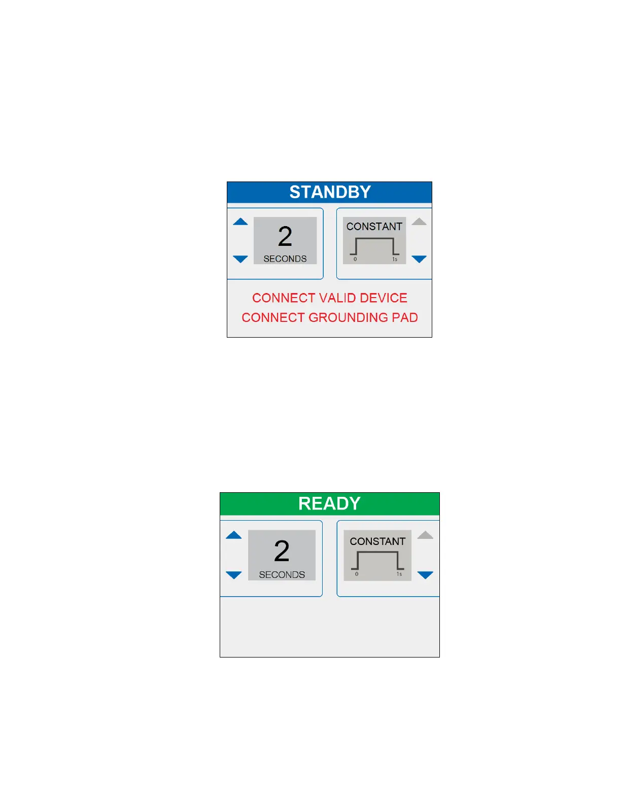
• The Standby State is initiated upon successful completion of the POST state.
• TIME and CUT settings can be adjusted with the left and right soft keys beside the
arrows.
• Messages instruct the user to connect a Valid Device and Return Electrode
(Grounding Pad).
• RF energy delivery cannot be initiated.
Figure 6-3- STANDBY State Display
6.3. READY State
• The Ready State is initiated when a Return Electrode (Grounding Pad) is connected
AND a valid device is connected OR when RF energy delivery is terminated.
• TIME and CUT settings can be adjusted with the left and right soft keys beside the
arrows.
• RF energy delivery can be initiated by either pressing the RF ON/OFF button or
pressing and holding FOOTSWITCH.
Figure 6-4a- READY State Display
 Loading...