© 2012-2019 Baylis Medical Company Inc. 15 of 48 DMR RFP-100A 3.3 V-13 29-May-2020_EN.docx
SECTION 5: CONTROLS, DISPLAYS, AND CONNECTIONS
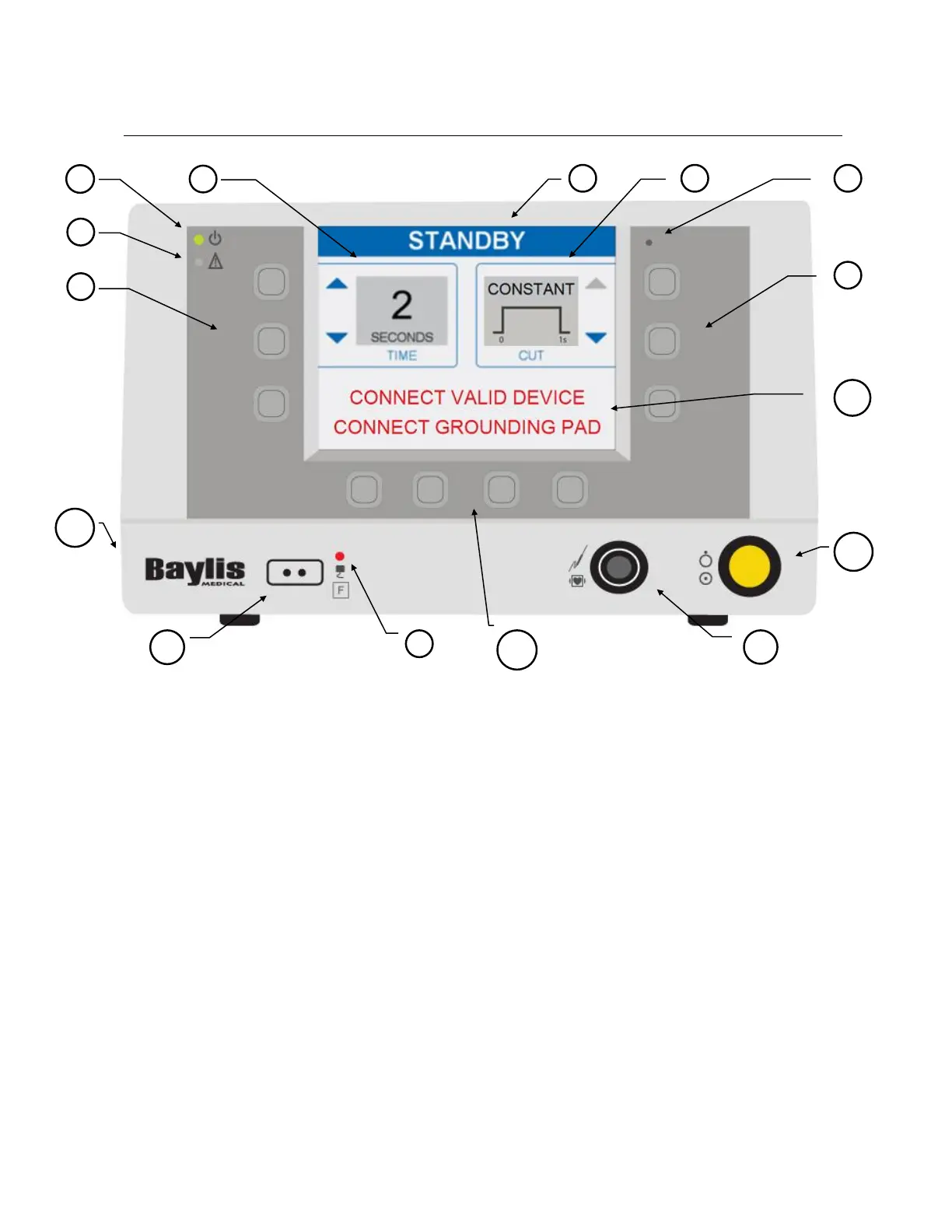
5.1. FRONT PANEL DISPLAYS, CONTROLS, AND CONNECTIONS
Descriptions of the front panel displays, controls, and connections are given below. Refer to
Figure 5-1 - Generator Front Panel for their location.
(1) AC Power Indicator: This green LED illuminates when the Generator is turned on.
(2) FAULT Indicator: This red LED illuminates and flashes when a system ERROR has
occurred. System errors include self-test failures, hardware protection errors, hardware
measurement errors, and software failures. Main power to the Generator must be cycled
(off-on) to attempt recovery from a system error. Consult instructions for use.
(3) Ambient Light Sensor: This sensor detects the ambient light level. Screen brightness is
automatically adjusted according to ambient light level (bright (HIGH) in a bright room
and dimmed (LOW) in a dim room).
(4) Return Electrode Fault Indicator: The red LED illuminates when a return electrode is
NOT connected to the generator OR when the measured impedance of a monitoring (dual
foil) return electrode is greater than 150 ohm, indicating poor patient contact. Note: Only
use return electrodes that meet or exceed IEC 60601-2-2:2017 requirements.