© 2012-2019 Baylis Medical Company Inc. 17 of 48 DMR RFP-100A 3.3 V-13 29-May-2020_EN.docx
5.2. REAR PANEL DISPLAYS, CONTROLS, AND CONNECTIONS
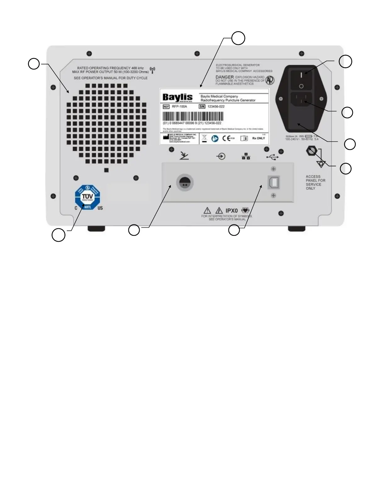
Descriptions of the rear panel displays, controls, and connections are given below. Refer to
Figure 5-2 - Generator Rear Panel for their location.
(1) AC Mains Switch: This switch controls the initial AC mains power input to the
Generator. It is part of the power entry module which also contains the fuse drawer and
AC power cord connector.
(2) AC Power Cord Connection: This connection is for the attachment of a hospital grade
power cord.
(3) Fuse Drawer: This fuse drawer contains the fuses that protect the generator from
excessive AC mains current.
(4) Equipotential Ground Connection: This connector is attached to the chassis/earth
ground. It is intended for earth reference connection in environments where equipotential
ground cabling is used.
(5) FOOTSWITCH Connection: This connection is for the attachment of the
FOOTSWITCH. Like the RF ON/OFF button, the FOOTSWITCH initiates and
terminates RF energy delivery. However, its action is different than the RF ON/OFF