EasyManua.ls Logo

Baylis RFP-100A - List of Tables; Generator Mode Settings; Table 9.2-1- CUT and TIME Settings for each Generator Mode

Default Icon
48 pages
Print Icon
To Next Page IconTo Next Page
To Previous Page IconTo Previous Page
Loading...
© 2012-2019 Baylis Medical Company Inc. 33 of 48 DMR RFP-100A 3.3 V-13 29-May-2020_EN.docx
9.2. GENERATOR MODE SETTINGS
The CUT and TIME settings that are available to the operator are dependent on the Generator
mode. The Generator mode is automatically selected when a BMC RF Device and its
specified Connector Cable is connected to the Generator.
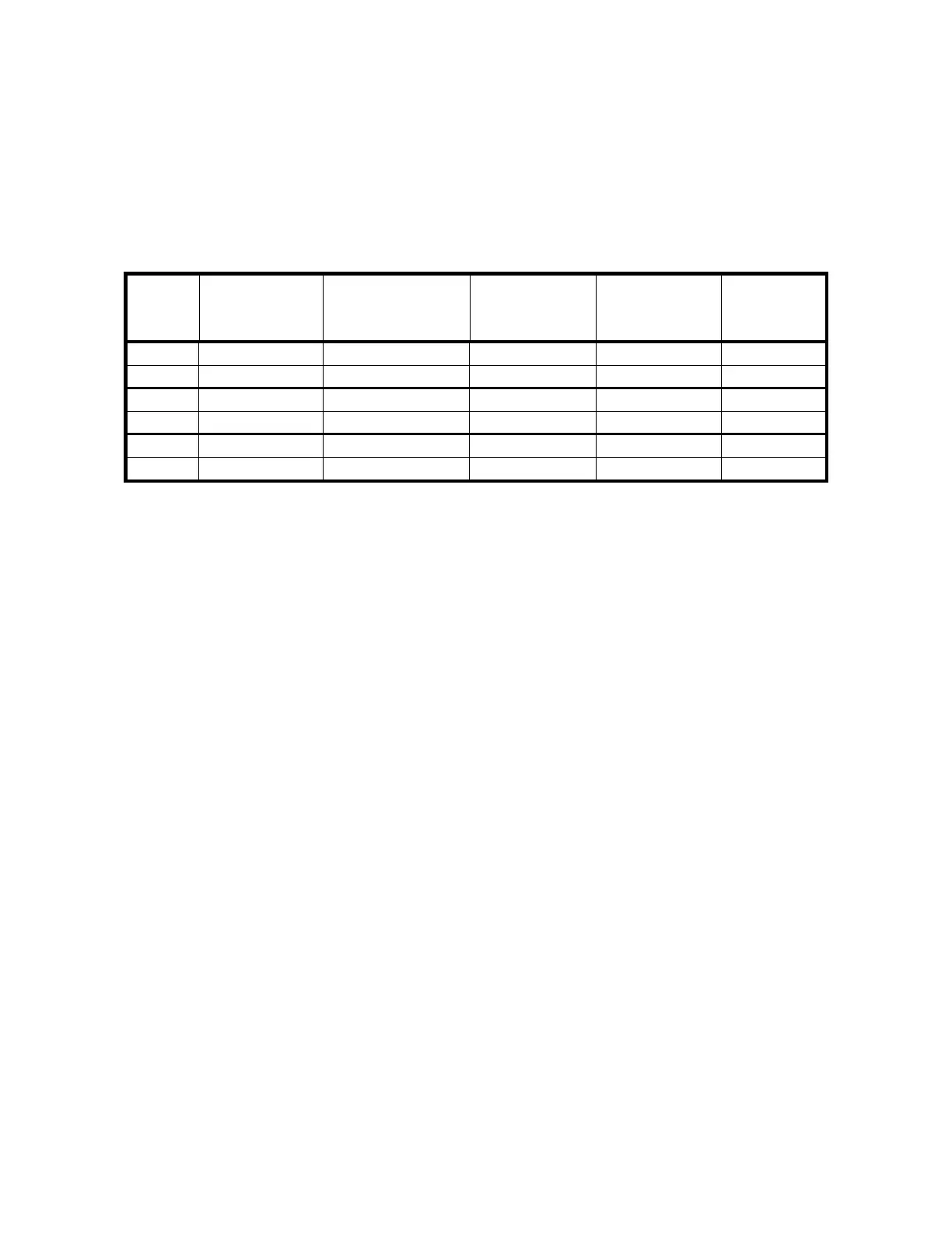
The table below provides the output parameters for each CUT and TIME setting available in
each Generator mode.
Table 9.2-1- CUT and TIME settings for each Generator Mode
Mode
#
CUT setting
Max Output
Voltage (V
rms
)
Pulse Duty
Cycle (%)
Pulse
Frequency
(Hz)
max TIME
(s)
10
Constant
300
100
1
3
Pulse
400
30
1
10
12
Constant
270
100
1
3
Pulse
270
30
1
10
14
STX Low
300
1.5
1
10
STX High
350
1.5
1
10

Table of Contents