MX610HD User’s Manual
MX610HD User’s Manual
Reset Button (Pin 5-7)
This 2-pin connector is for the chassis-mounted reset button for system reboot without
turning off the system power.
Power LED (Pin 2-4)
This 2-pin connector is for the system power LED. Connect the chassis power LED cable
to this connector. The system power LED lights up when you turn on the system power,
and blinks when the system is in sleep mode.
Hard Disk Drive Activity LED (Pin 1-3)
This 2-pin connector is for the HDD Activity LED. Connect the HDD Activity LED cable to
this connector. The IDE LED lights up or flashes when data is read from or written to the
HDD.
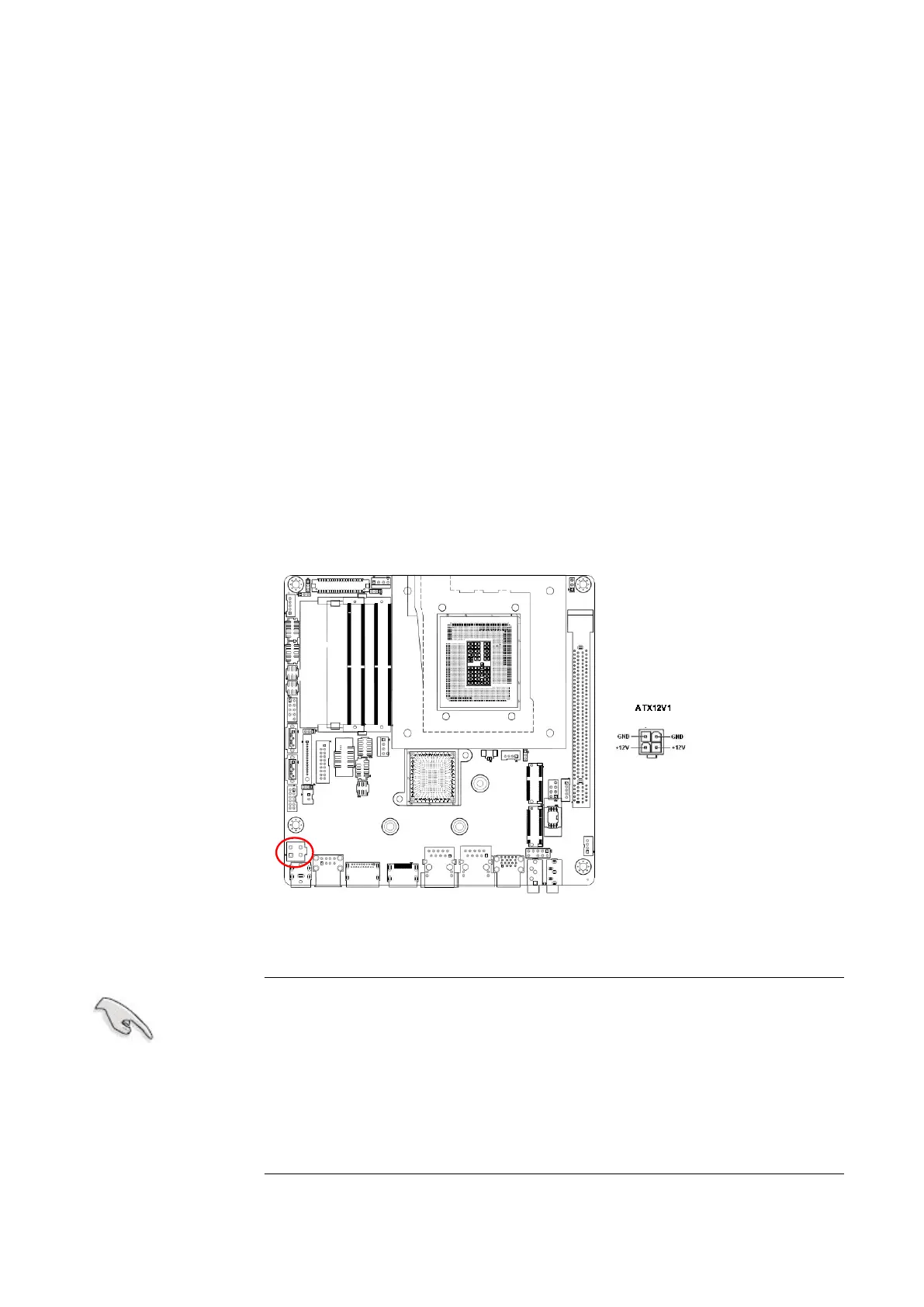
1.7.4 ATX power connectors (ATX12V1)
The connector is for ATX power supply plugs. The power supply plugs are designed to fit
these connectors in only one orientation. Find the proper orientation and push down firmly
until the connectors completely fit.
Use of a PSU with a higher power output is recommended when
configuring a system with more power-consuming devices. The
system may become unstable or may not boot up if the power is
inadequate.
Make sure that your power supply unit (PSU) can provide at
least the minimum power required by your system. See the
table below for details.