11
Part No. 6-847681-00 Rev. D
Rough-In Installation
Pipeline Connections
1. Braze the copper extension tubes from the
rough-in assembly to the appropriate
gas/vacuum piping system drops. Braze the
connections per the procedures required by
NFPA 99 or CAN/CSA-Z305.1. Use
appropriate measures to prevent overheating
and damage to the internal components of the
gas/vacuum service rough-in assemblies.
2. Perform standing pressure tests and cross-
connection tests as required by NFPA and
CSA. Note that vacuum service rough-in
assemblies include a plastic plug to permit
system testing under vacuum.
Dust Covers
1. Install the dust covers to protect the alarm
during the finishing of the walls. Refer to
Figure 8.
Figure 8. Install Dust Covers
Dust covers
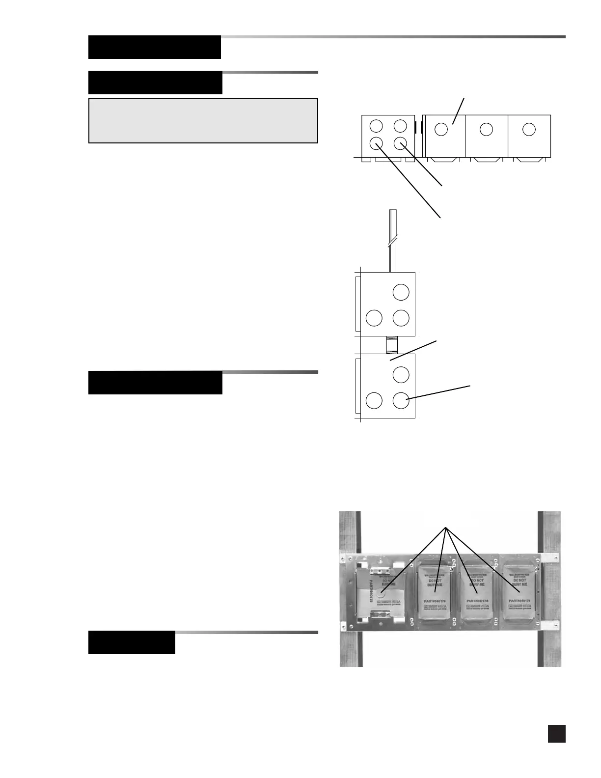
Electrical Connections
1. Connect the power supply conduit from the
life safety branch of the building emergency
power system to the power supply mounting
box using the knockout shown in Figure 7.
2. If alarm panels are to be networked, connect
the conduit for the network wiring to the
power supply mounting box using the
knockout shown in Figure 7.
3. If using remote sensors or switches, connect
the conduit for external signal wiring to the
alarm mounting box using the knockout
shown in Figure 7.
NOTE:
Refer to Wiring Installation to determine the quantity
and routing of alarm signal wires.
Power supply wiring
120 VAC 50/60 Hz
Network wiring
Remote sensor or
switch wiring
Right side of alarm panel
Top of alarm panel
Figure 7. Knockouts