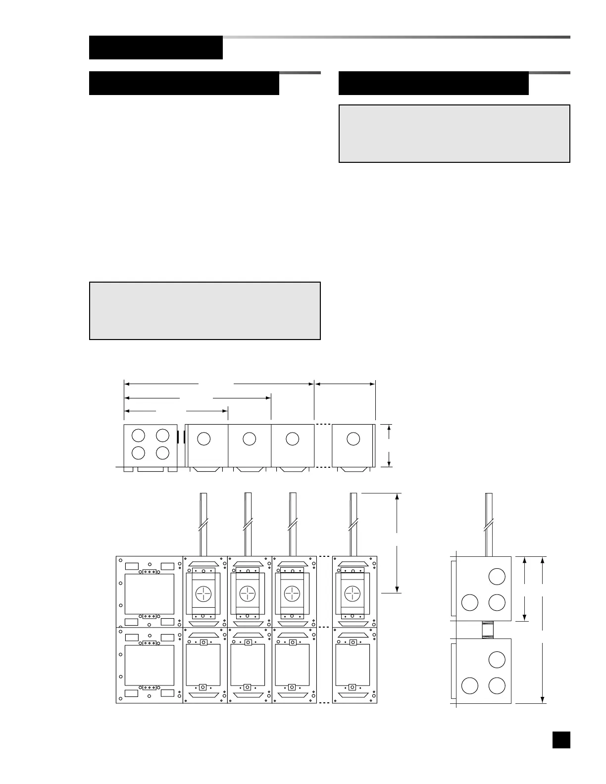
Figure 5. Rough-In Dimensions
9
Part No. 6-847681-00 Rev. D
Rough-In Installation
Gas/Vacuum Service Rough-In
1. Remove the small knockout from the top
of each sensor module mounting box.
2. Insert the gas/vacuum service rough-in
assembly into the mounting box and
secure with (2) #6-20 x 1/4” screws.
Refer to Figure 4.
Sensor Module Rough-In Boxes
NOTE:
Gas/vacuum service rough-in assemblies are gas specific.
Be sure to install the gas/vacuum service rough-in in the
correct order according to the building plans.
Remote sensor modules may be installed
as individual units or ganged in a panel
configuration.
1. If sensor modules are to be ganged,
attach the mounting boxes together using
(2) #6-20 x 1/4” screws.
2. Install end panels to each end of the
assembled mounting boxes or to the
sides of each mounting box if installed as
individual units.
NOTE:
Sensor modules receive power from their corresponding
digital display modules. A separate power supply module
is not required for remote sensors.