31
Part No. 6-847681-00 Rev. D
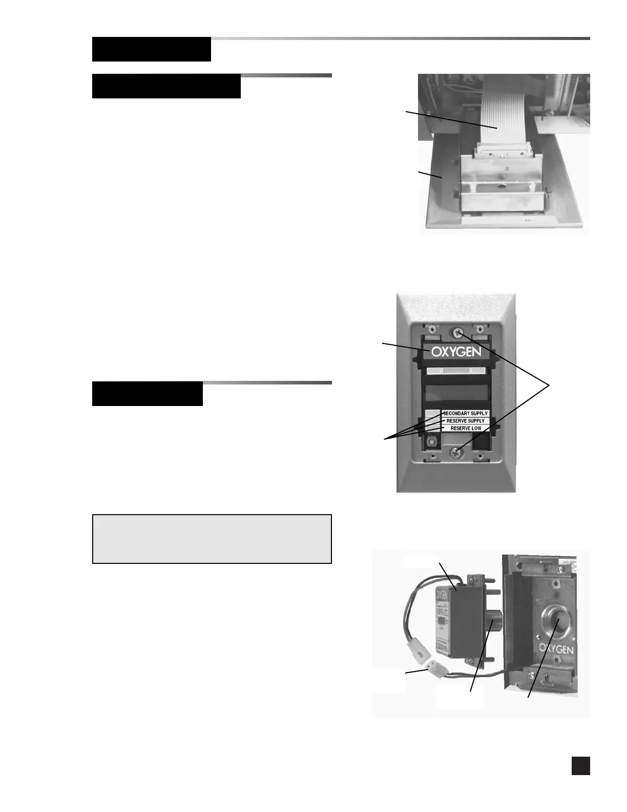
Finish Installation
Sensor Module
Digital Display Module
1. Remove the dust cover from the
mounting box.
2. Connect the twenty-wire ribbon cable
from the interconnect board to the digital
display module chassis. Refer to Figure
13.
3. Install the digital display module chassis
into the mounting box using (2) #6-32 x
1-1/2” screws. Do not tighten. Refer to
Figure 14.
4. If user-assigned signal inputs are in use,
install system status labels. Refer to
Figure 14.
Figure 14
Figure 13
#6-32 x
1-1/2”
screws
Twenty-wire
ribbon cable
System
status
labels
Gas ID
label
Digital display
module chassis
1. Remove the dust cover from the
mounting box.
2. Join the polarized connector in the
mounting box to the mating connector on
the sensor. Refer to Figure 15.
3. Insert the sensor into the valve opening in
the gas/vacuum service rough-in. An
indexing pin provides for proper
orientation and prevents gas service
cross-connection. Push the sensor all the
way in and secure with (2) #6-32 x 3/4”
screws.
4. Tuck excess wiring into the open space
behind the sensor.
Figure 15
Polarized
connector
Sensor
IMPORTANT:
Remove the blue protective netting from the sensor
connector.
Sensor
connector
Valve
opening