8
Part No. 6-847681-00 Rev. D
Rough-In Installation
9. Install a 1/2” x 2” pipe nipple (supplied by
others) between digital display module
mounting boxes and sensor module
mounting boxes. Refer to Figure 4.
10. Place the top of each lower mounting box
over the bottom of each upper mounting
box and attach with (2) #6-20 x 1/4”
screws per pair of mounting boxes.
Refer to Figure 3.
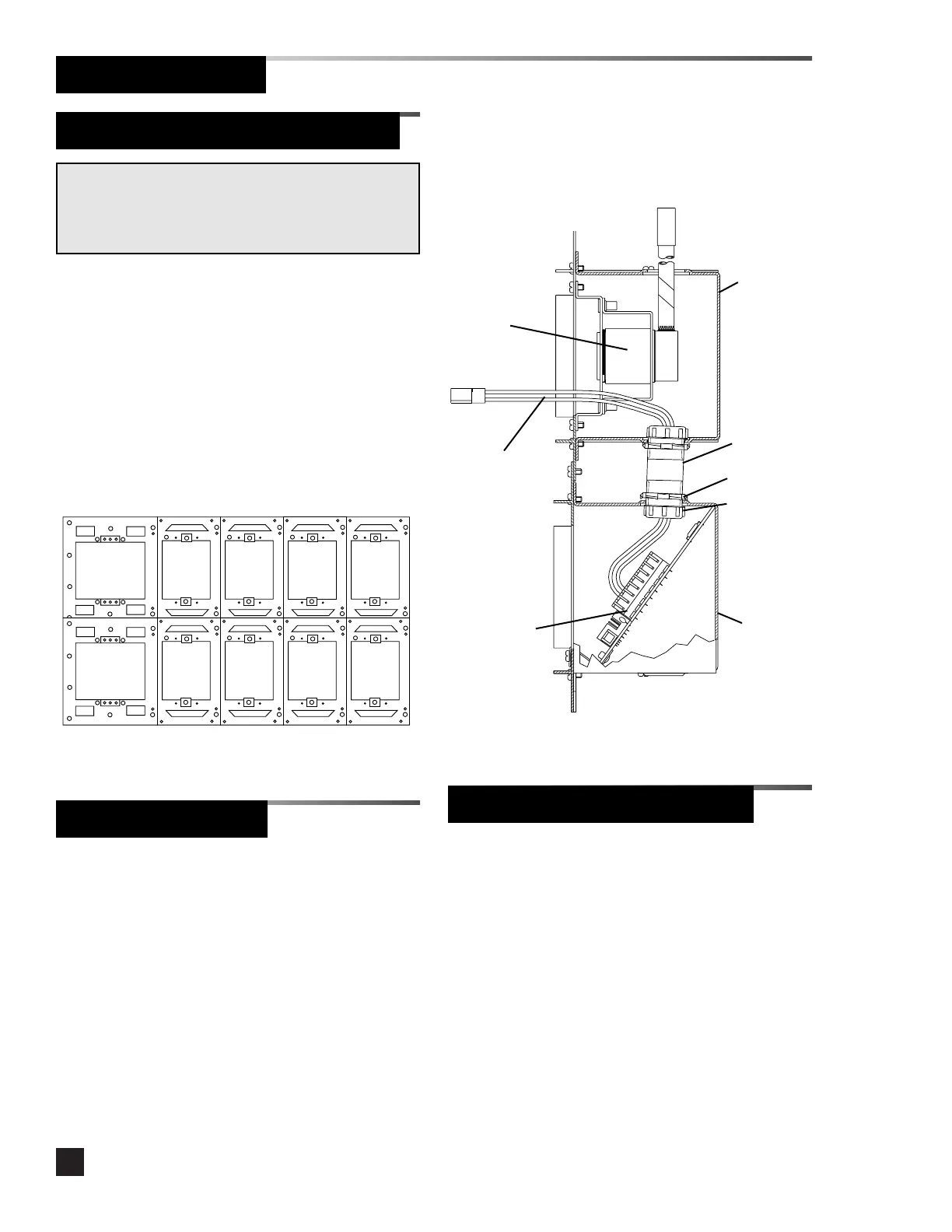
Figure 4. Local Sensor Rough-In Detail
1/2” x 2”
pipe nipple
(2) Locknuts
(2) Bushings
Figure 3. Attach Mounting Boxes
Sensor
module
mounting
box
Digital
display
module
mounting
box
NOTE:
If the alarm panel has local sensor modules, they should
be mounted directly above the corresponding digital
display modules.
Alarm Panel Rough-In Boxes (Cont.)
1. Locate the interconnect board for the
module to be installed adjacent to the
power supply module.
2. Insert the end of the ten-wire ribbon
cable through the grommeted opening in
the lower left side of the mounting box
and into the power supply mounting box.
3. Install interconnect boards into alarm
mounting boxes using (2) #6-20 x 1/4”
screws. Refer to Figure 4.
Interconnect Boards
Sensor Pigtail (Local Sensors)
Interconnect
board
4. Connect the ten-wire ribbon cable to the
plug on the adjacent interconnect board.
Gas/vacuum
service
rough-in
Sensor
pigtail
1. Route the sensor pigtail through the pipe
nipple. Refer to Figure 4.
2. Install the red wire into the T+ terminal
(Terminal block 2, terminal 6) on the
digital display module interconnect board.
To install the wire, use a small flat
screwdriver to depress the lever on the
terminal block.
3. Install the black wire into the T- terminal
(Terminal block 2, terminal 7).