34
Part No. 6-847681-00 Rev. D
Operation
Start-Up and Checking
1. Turn on electrical power to the alarm
panel.
2. Make the following observations:
•The POWER ON light illuminates on
the power supply module.
•Digital display modules and multi-
signal alarm modules warm-up for ten
seconds. During the warm-up no
alarms sound and all LEDs indicate
normal. After the warm-up period any
alarm conditions activate.
•Multi-signal alarm modules indicate a
red LED and audible alarm for any
signals with open switches or unused
signals.
3. Press the SILENCE button on EACH
alarming module to silence the audible
alarms.
4. Pressurize the piping system (medical gas
and vacuum).
5. Make the following observations:
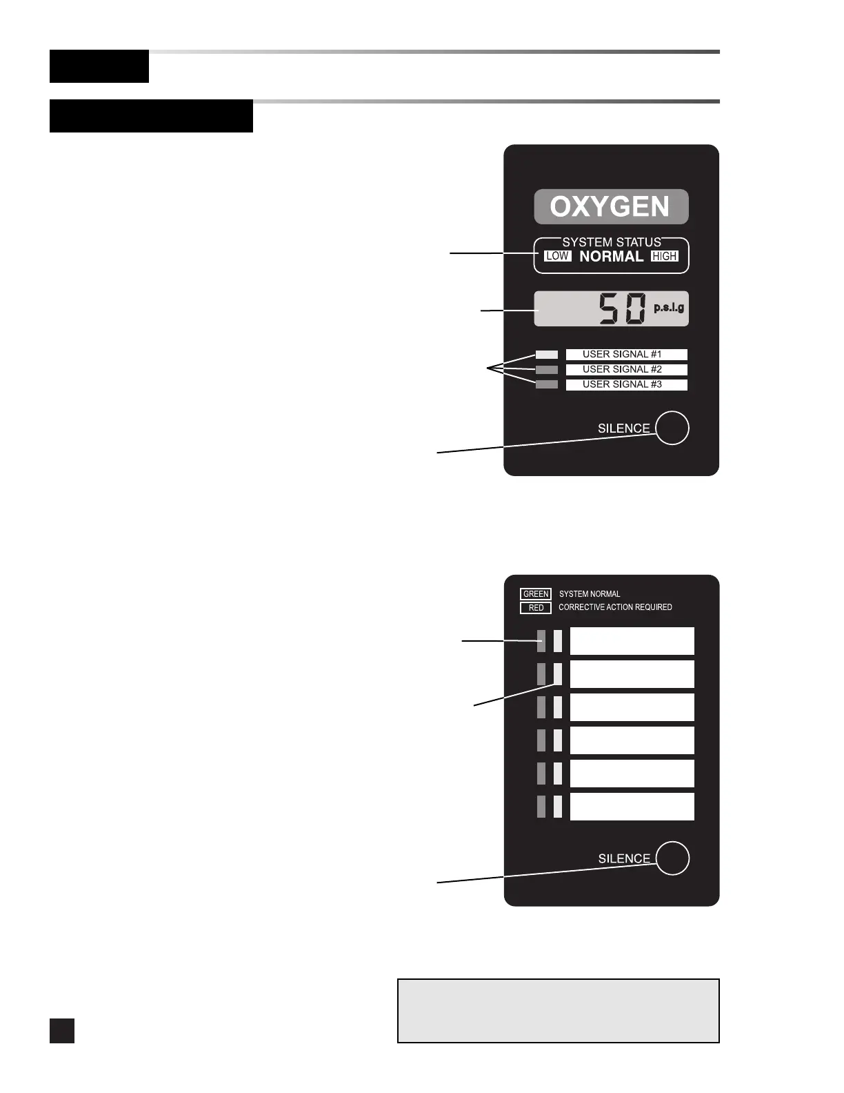
•Digital display module LCDs display
the actual pipeline pressure or
vacuum levels.
•If the levels are within pre-set limits,
the system status indicators show
NORMAL.
•If the pressure or vacuum level is
outside the pre-set limits, the system
status indicators show HIGH or LOW.
•If a fault code is displayed (-F1-, -F2-,
or -F3-) refer to Tro ubles hoo ting
Guide.
•If wired, digital display module user-
assigned signals indicate the current
status from dry-contact switches.
•Multi-signal alarm modules indicate
the current status from dry-contact
switches. Unused signals can be
disabled. Refer to Set-Up
Procedure.
System
status
indicators
Liquid Crystal
Display (LCD)
User-assigned
signal
indicators
SILENCE
button