32
Part No. 6-847681-00 Rev. D
Multi-Signal Alarm Module
Computer Interface Relay Module
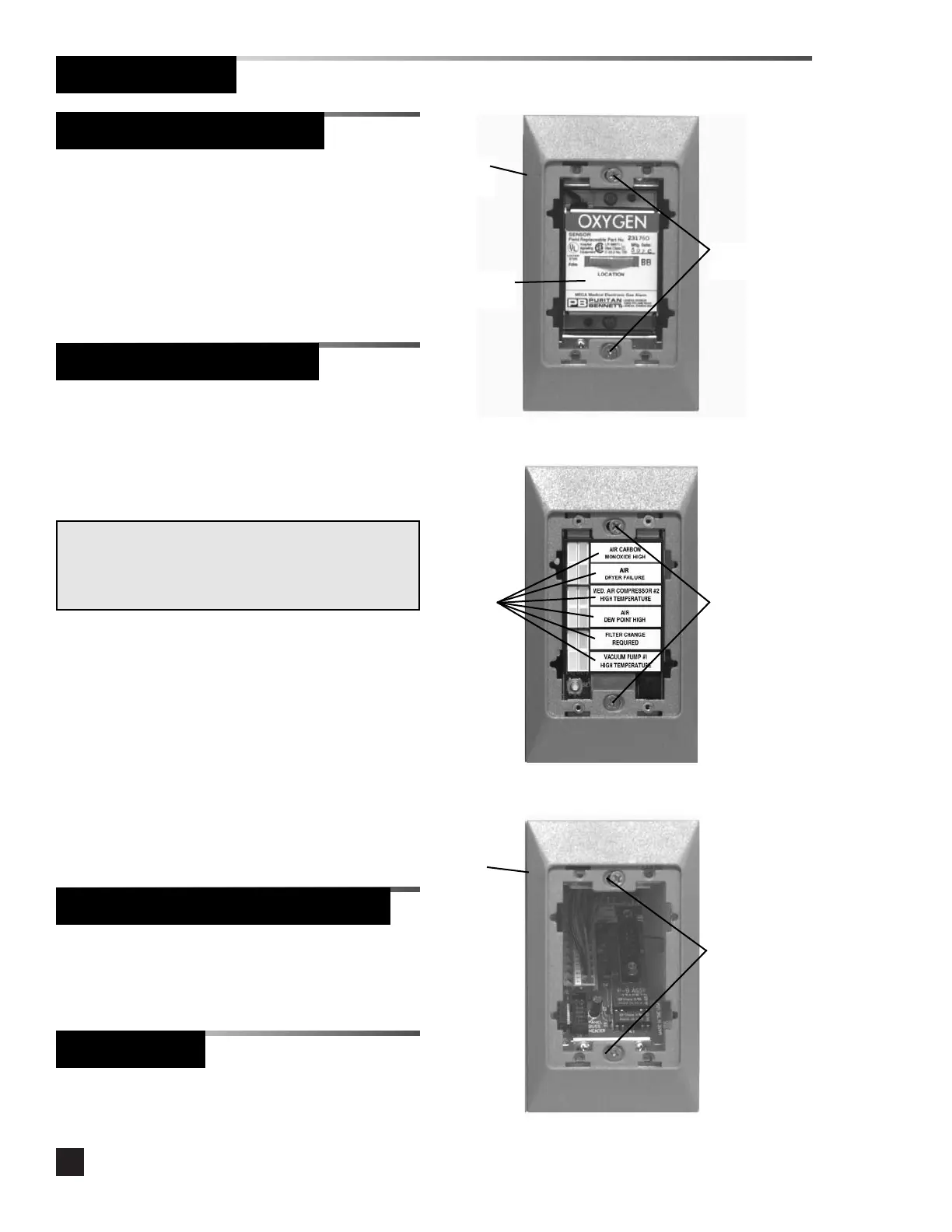
5. Mark the location monitored by the
sensor in the space provided on the
sensor label. Refer to Figure 16.
6. Install trim plate using (2) #6-32 x 1-1/2”
screws. Do not tighten. Refer to Figure
16.
1. Install trim plate using (2) #6-32 x 1-1/2”
screws. Do not tighten. Refer to Figure
18.
Figure 16
Trim
plate
System
status
labels
Figure 18
Location
label
#6-32 x 1-1/2”
screws
Trim
plate
#6-32 x 1-1/2”
screws
1. Remove the dust cover from the
mounting box.
2. Install system status labels on the multi-
signal alarm module chassis.
3. Connect the sixteen-wire ribbon cable
from the multi-signal alarm module
interconnect board to the connector on
the back of the multi-signal alarm module
chassis.
4. Install the multi-signal alarm module
chassis into the mounting box using (2)
#6-32 x 1-1/2” screws. Do not tighten.
Refer to Figure 17.
NOTE:
The system status label sheet contains the most typical
messages and additional blank labels for user-specific
messages.
Figure 17
#6-32 x 1-1/2”
screws
Blank Module
1. Install trim plate using (2) #6-32 x 1-1/2”
screws. Do not tighten.
Finish Installation
Sensor Module (Continued)