30
Part No. 6-847681-00 Rev. D
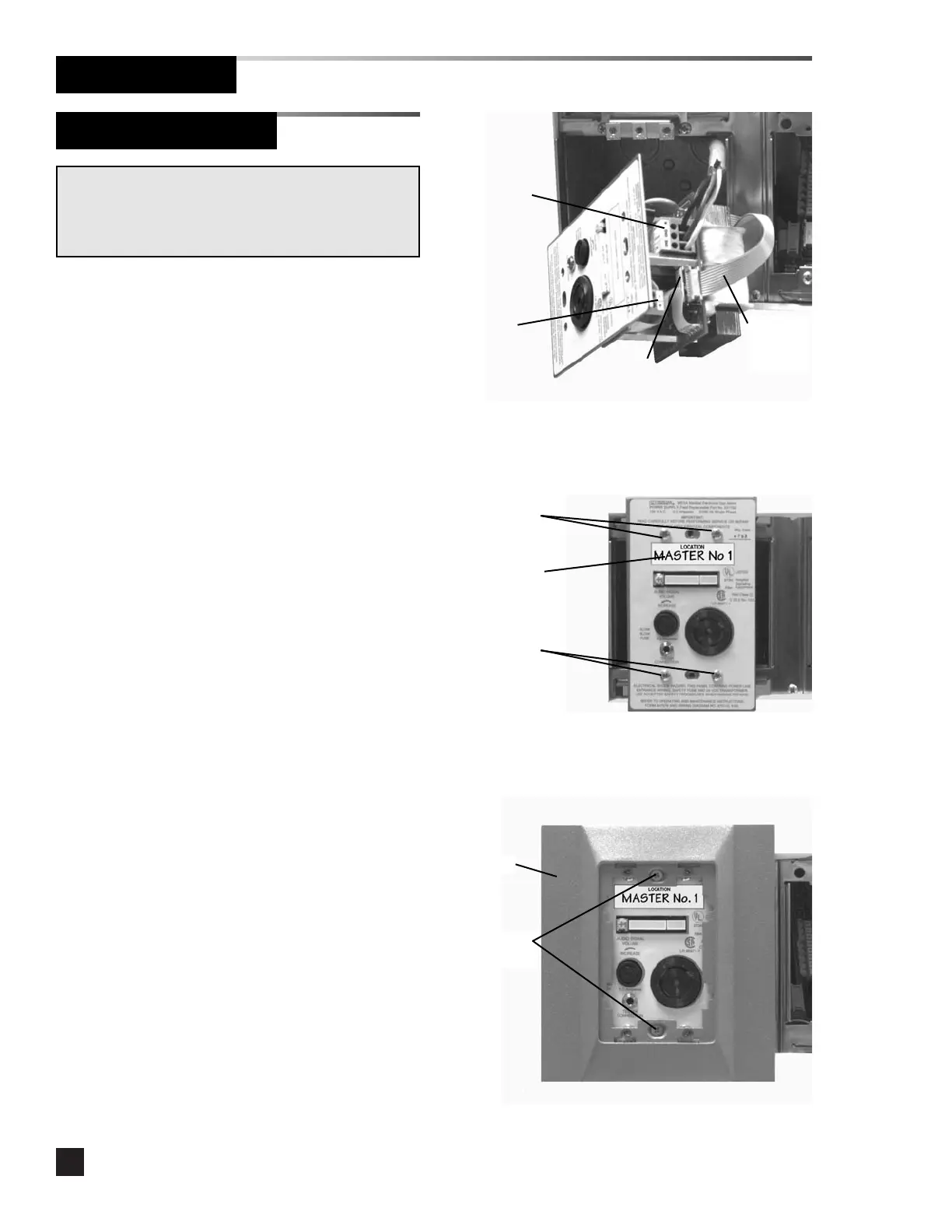
Power Supply Module
Finish Installation
1. Remove the dust cover from the
mounting box.
2. Strip 1/4” insulation from LINE, GROUND
and NEUTRAL leads and insert into the
appropriate terminals on the POWER
SUPPLY TRANSFORMER terminal block.
Tighten the terminal screws. Refer to
Figure 10 and Schematic 1.
3. Connect the ten-wire ribbon cable from
the adjacent module to the connector
labeled ALARM CONNECTION on the
power supply chassis. Refer to Figure 10
and Schematic 1.
4. If alarms are to be networked, strip 1/4”
insulation from network leads and insert
into the appropriate terminals on the
COMPUTER INTERFACE terminal block.
Tighten the terminal screws. Refer to
Figure 10 and Schematic 10.
6. Install the power supply module chassis
in the mounting box and secure with (4)
#6-32 x 9/16” screws. Refer to Figure
11.
7. Install the location label. Refer to Figure
11.
8. Install the trim plate using (2) #6-32 x
3/4” screws. Do not tighten. Refer to
Figure 12.
WARNING: SHOCK HAZARD
Verify supply voltage is turned off at circuit breakers prior
to connection of power supply module. Serious injury or
death can result from electrical shock.
Power supply
transformer
terminal block
#6-32 x 9/16”
screws
Ten- w i re
ribbon
cable
Computer
interface
terminal block
Alarm
connection
Figure 10
Figure 11
Figure 12
Location label
#6-32 x 9/16”
screws
#6-32 x 3/4”
screws
Trim plate