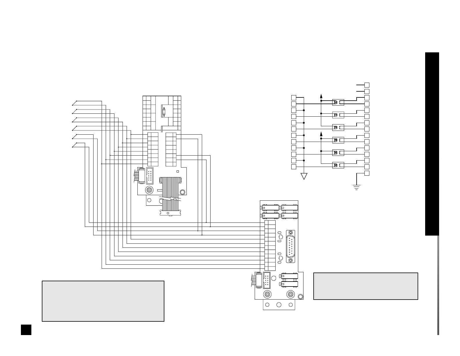
EasyManua.ls Logo

Beacon MEGA - Computer Interface Relay Module Wiring

Default Icon
52 pages
Print Icon
To Next Page IconTo Next Page
To Previous Page IconTo Previous Page
Loading...
+
COM
+
COM
+
COM
+
COM
COM
COM
+
+
Ground
Terminal Block
Relay Outputs to Building Computer
15-Pin Connector
1
2
3
4
5
6
7
8
9
10
11
12
1
2
3
4
5
6
7
8
9
10
11
12
13
14
15
Common
Signal 1
Signal 2
Signal 3
Signal 4
Signal 5
Signal 6
Alarm 1
(Cable Shield)
Alarm 2
Alarm 3
Alarm 4
Alarm 5
Alarm 6
Common
Common
Common
Common
Common
Signal
Return
Signal
Signal
Signal
Signal
Signal
Earth
Return
Return
Return
Return
Return
+5 VDC
+5 VDC
231957
J3
J1
J2
TB1
C5
C4
U1
U2
+
C1
C7C6
K2
K1
K3
K4
C11
K6
K5
C10
PANEL
BUSS
CABLE
PANEL
BUSS
HEADER
DATE CODE
MADE IN THE USA
P-B ASSY
15
8
9
1
123456
7 8 9 10 11 12
C2
C3
C8
C9
J3
SCREWDRIVER TO DEPRESS
USE SMALL FLAT BLADE
8
18
1
231955
P-B ASSY
INTERCONNECT CABLE
MULTI-SIGNAL MODULE
MADE IN THE USA
CABLE
BUSS
PANEL
HEADER
BUSS
PANEL
INPUTS
H
C
T
I
W
S
ALARM
DC/AC
2A 30V
RATING
RELAY
SIGNAL
EXT
3A
NO
COM
NC
EARTH GROUND
6
54
3
2
1
COM
COM
+
+
+
+
+
+
COM
COM
COM
COM 7
6
5
4
3
2
1
1
2
3
4
5
6
7
8
TERMINAL BLOCK 2TERMINAL BLOCK 1
F1
J1
J2
8
123456
78
87
654321
DATE
Alarm Signal Inputs
NOTE 2:
Relay contacts are normally closed.
Contacts open when alarm occurs.
Multi-signal alarm module
interconnect board
Computer interface relay module
interconnect board
Schematic 7. Computer Interface Relay Module
Computer interface relay module schematic
NOTE 1:
Wiring shown with multi-signal alarm module.
The computer interface relay module can also
be used to relay the three user-assigned
signals on a digital display module.
Supply Status
Signal Switches
SIGNAL 1
SIGNAL 2
SIGNAL 3
SIGNAL 4
SIGNAL 5
SIGNAL 6
21
Part No. 6-847681-00 Rev. D02
Wiring Schematic: Computer Interface Relay Module
Ten- w i r e r i b bon
cable to adjacent
module

Table of Contents