IPC@CHIP DK41 / DK51
Getting Started V2.2
© 2000-2004 Beck IPC GmbH Page 5 of 61
2.1.2 Step 1 – Switching on the DK40 Development Board
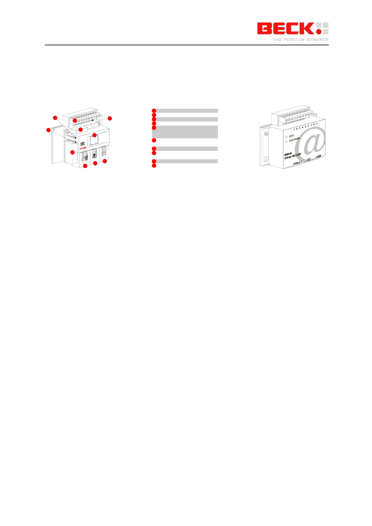
The DK40 Development Board is an evaluation platform for the Embedded Controller SC12. It
provides two serial ports, an Ethernet interface, eight digital I/O, a ‘link/traffic’ LED, a free
programmable LED and a switching DC/DC converter (15 ... 30V -> 5 V).
1
2
3
4
5
6
7
8
9
10
Free programmable user LED
1
Combined link/traffic/reset LED
2
Network transformer for twisted pair
3
Interference capacitor4
Socket strip with screw terminal for
voltage supply and combined
inputs/outputs
5
Control LEDs for combined
inputs/outputs
6
IPC @CHIP SC10/SC11/SC12
7
Twisted pair network connection
for 10Base T
8
EXT interface
9
COM interface10
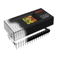
First of all, you have to place the SC12 into the socket inside the DK40. The small dot on the top of the
SC12 diagonally opposite to the BECK logo indicates pin 1. The notch in the socket indicates the
position of pin 1 in the socket. Please also refer to the drawing of the DK40 and make sure you insert
the chip with the correct orientation.
Connect the power supply (24 VDC) to the DK40 socket strip. GND must be connected to the pin
marked "-". +24 VDC must be connected to the pin marked '+'.