Mounting and cabling
EL6752 23Version: 2.1
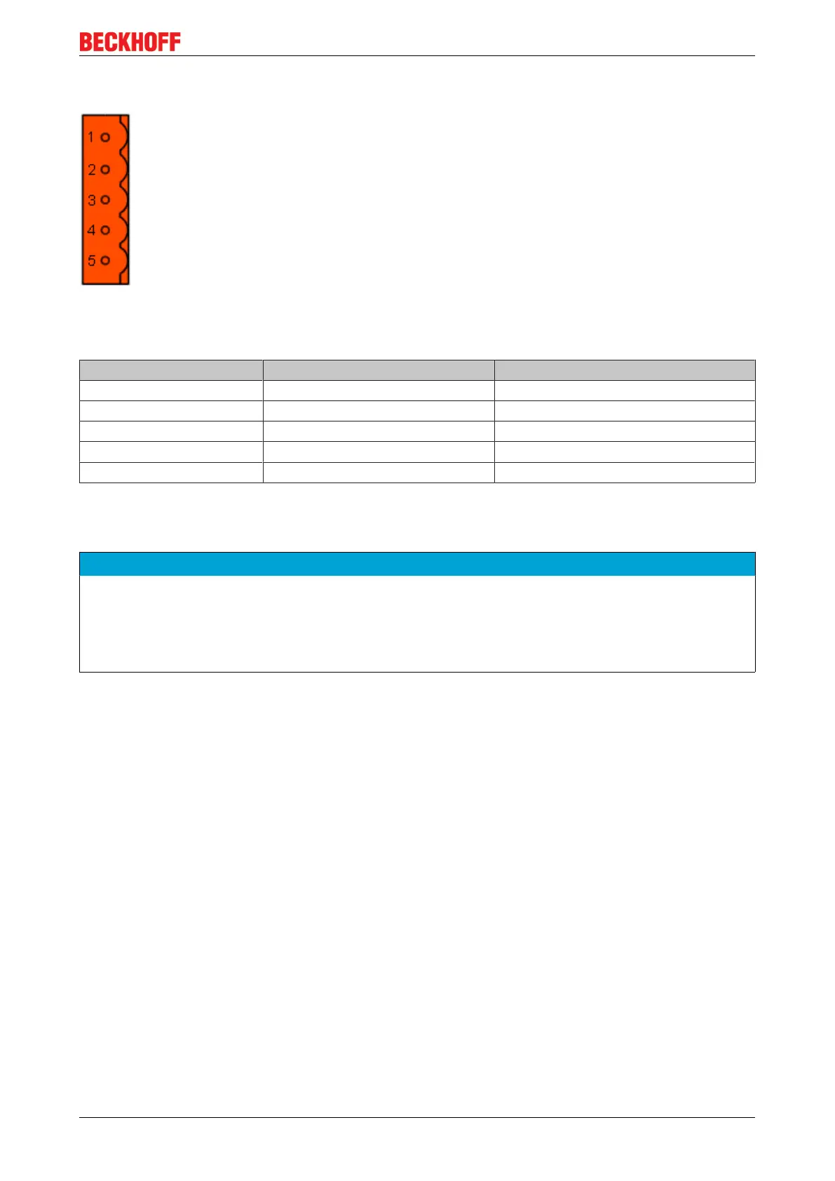
4.5.7 Cable colours and pin assignment
Fig.17: Pin assignment (top view EL6752)
Suggested method of using the Beckhoff CAN cable on Bus Terminal and Fieldbus Box:
Pin EL6752 assignment ZB5200 cable color
1 V+ (24 V) red
2 CAN High white
3 Shield Filler strand
4 CAN Low blue
5 V- black
4.6 Installation positions
NOTE
Constraints regarding installation position and operating temperature range
Please refer to the technical data for a terminal to ascertain whether any restrictions regarding the installa-
tion position and/or the operating temperature range have been specified. When installing high power dissi-
pation terminals ensure that an adequate spacing is maintained between other components above and be-
low the terminal in order to guarantee adequate ventilation!
Optimum installation position (standard)
The optimum installation position requires the mounting rail to be installed horizontally and the connection
surfaces of the EL/KL terminals to face forward (see Fig. “Recommended distances for standard installation
position”). The terminals are ventilated from below, which enables optimum cooling of the electronics through
convection. "From below" is relative to the acceleration of gravity.