21Bend-Tech Dragon A400
Powered Gate Retrot Guide
Installation Guide
02
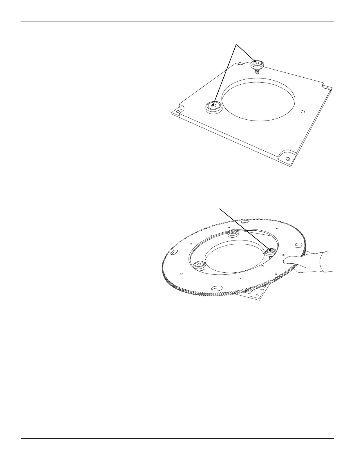
5. Bearing Installation
Locate the new Powered Gate Mount
Plate. Place the Powered Gate Mount
Plate so the mounting pins are facing
down and the two threaded holes for
v-groove bearings that were removed in
Step 4.
Apply Loctite Blue 242 to the threads of
them on the new Gate Mount Plate.
Using the provided ¾ in. thin wrench,
tighten the bearings securely by hand.
6. Gate Ring Gear
Locate the new Gate Ring Gear.
Ensuring the C Axis Homing Sensor
bolt head is down, place the Gate
Ring Gear over the new Gate
Mounting Plate and position it so the
v-shaped inner bearing surface is
bottomed out in the v-groove of the
With one hand, pull the Gate Ring
v-groove bearings. With a free hand,
position the v-groove eccentric
bearing so it is over its mounting
hole, then place the v-groove
eccentric bearing so its v-groove
is seated on the v-shaped inner
bearing surface of the Gate Ring Gear.
bearings into the threaded
holes.
Position the v-groove of the
eccentric bearing on the inner
ring while holding the Ring
Gear at an angle.