EasyManuals Logo

Bend-Tech Dragon A400 User Manual

Bend-Tech Dragon A400
35 pages
To Next Page IconTo Next Page
To Previous Page IconTo Previous Page
Page #31 background imageLoading...
Page #31 background image
31Bend-Tech Dragon A400
Powered Gate Retrot Guide
Installation Guide
02
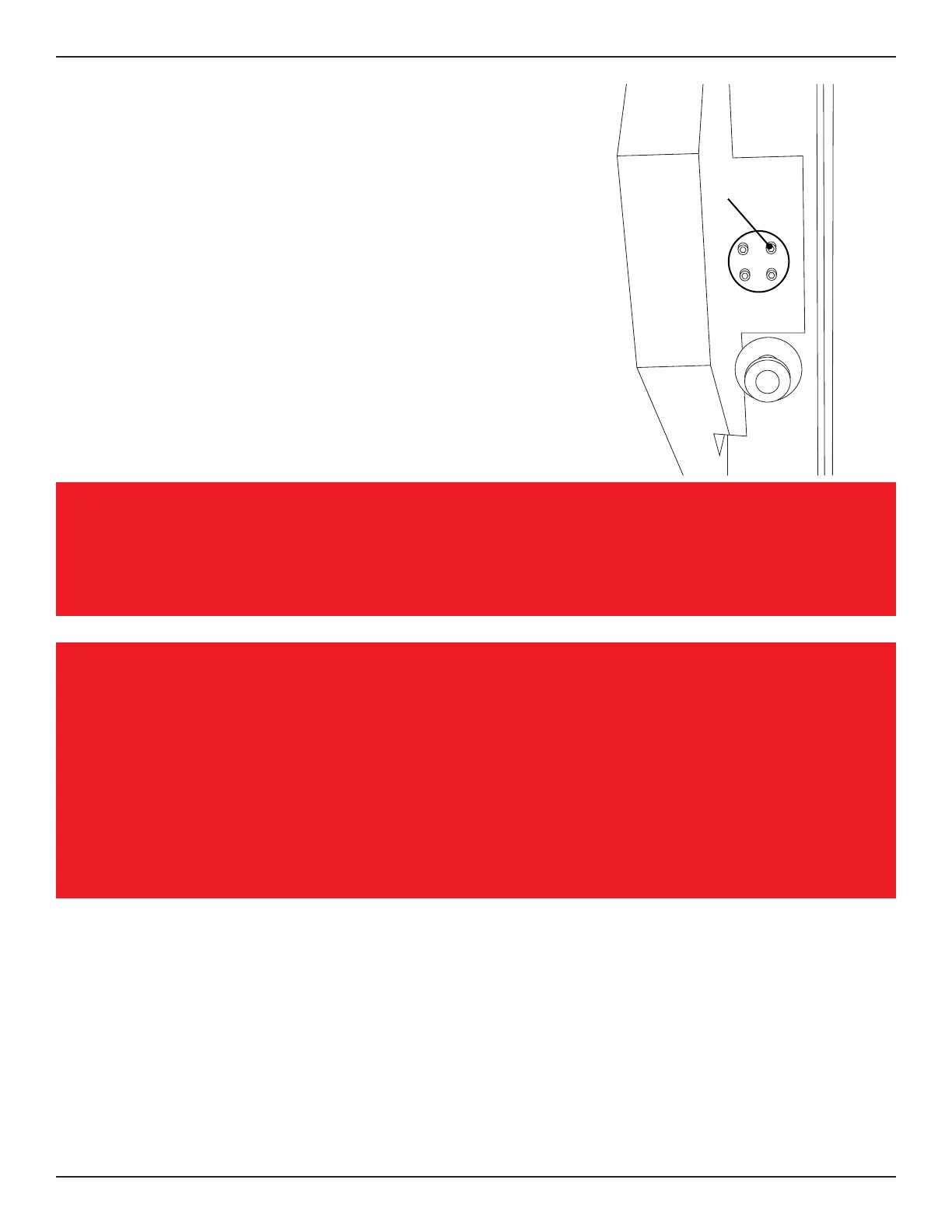
The left side Gate Ring Gear Safety Guard attaches
to the Head of the machine using the four Gate
Clamp fastener holes. If the Gate Clamp is still
installed on the Head of the machine, remove it
at this time. Place the guard in position and install

inside the Head of the machine, place the 4



wrench.
Important
The Powered Gate does not require the use of the Gate Clamp.
Note
On some machines there may not be holes in place for the Gate Clamp. If this
is the case, the Installer will need to drill holes in order to mount the left Gate
Ring Gear Safety Guard. Use the Drill Template provided with the Powered Gate

bolt. Ensure the arrow on the Drill Template is pointed toward the front of the
machine. Drill the four holes using a 1/4 in. drill bit.

head screws

Other manuals for Bend-Tech Dragon A400

Questions and Answers:

Question and Answer IconNeed help?

Do you have a question about the Bend-Tech Dragon A400 and is the answer not in the manual?

Bend-Tech Dragon A400 Specifications

General IconGeneral
BrandBend-Tech
ModelDragon A400
CategoryIndustrial Equipment
LanguageEnglish

Related product manuals