SettingsSettings
iso685-D-P_D00170_00_M_XXDE/06.2016
50
10.1 1.10.6 Analogue
The following parameters can be set for the analogue output:
10.1 1.10.6.1 Mode
The following values can be set for the operating mode of the analogue output
Current output
•0-20 mA
Permissible load ≤ 600 Ω
•4-20 mA
Permissible load ≤ 600 Ω
•0-400
μA
Permissible load ≤ 4 kΩ
Voltage output
•0-10 V
Permissible load ≥ 1 kΩ
•2-10 V
Permissible load ≥ 1 kΩ
10.1 1.10.6.2 Midscale
Select the appropriate midscale. The following parameters can be set:
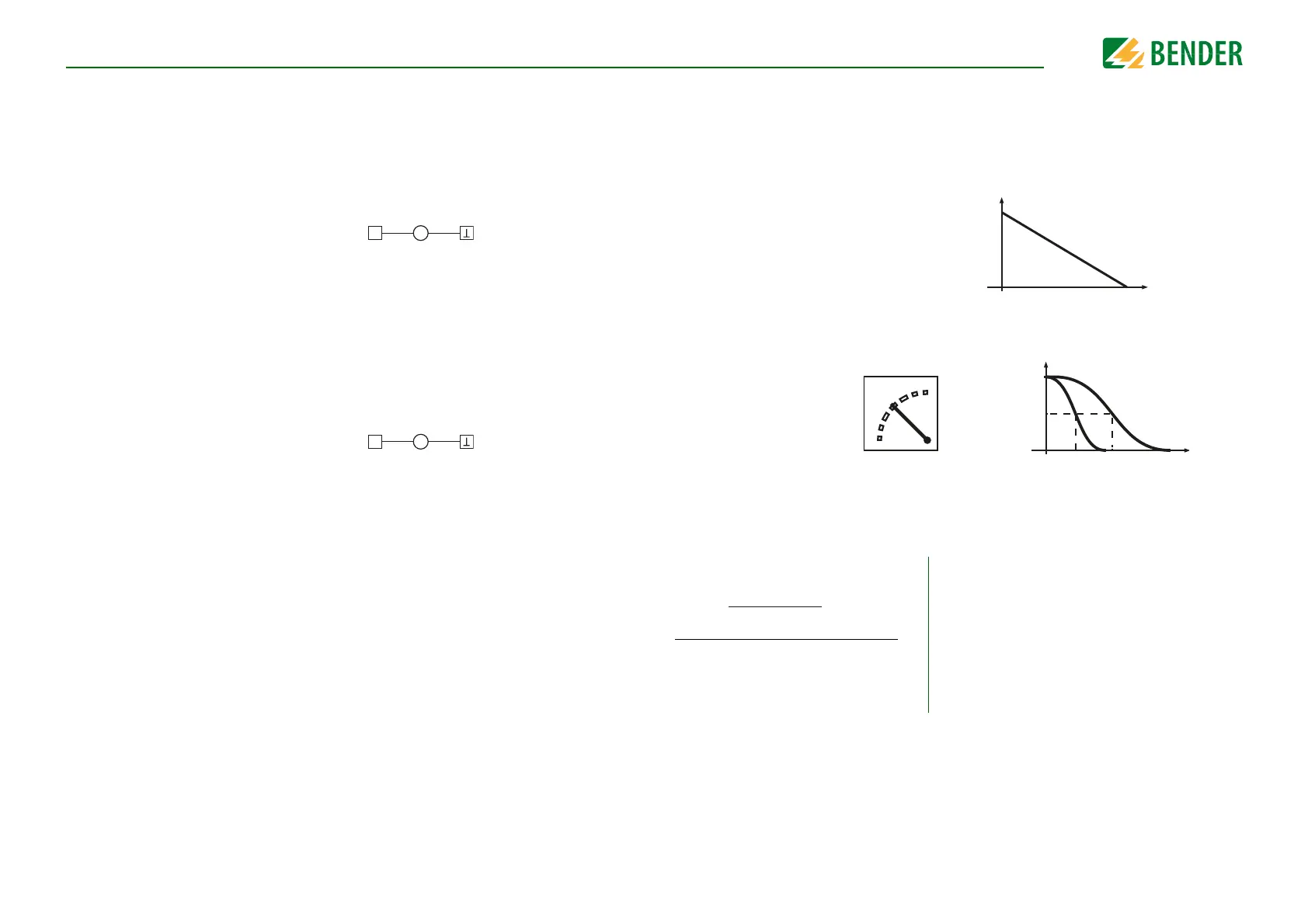
Calculation of the insulation resistance using the analogue output:
•Linear
The switching signal is linear to the insulation resistance in
the indicated measuring range.
•28 k
Ω
•120 k
Ω
The switching signal is analogue to the mid scale of 28 kΩ
or 120 kΩ on a measuring instrument.
Lower value
Analogue output A
1
0 mA
4 mA
0 µA
0 V
2 V
Upper value
Analogue output A
2
20 mA
20 mA
400 µA
10 V
10 V
10 kΩ 1 MΩ
I/U20 mA / 400 µA
10 V
0 mA / 4 mA
0 V / 2 V
1 k
1 M
100
100 k
Ω
28 kΩ
120 k Ω
100 Ω 1 MΩ
I/U20 mA / 400 µA
10 V
0 mA / 4 mA
0 V / 2 V
120 k Ω28 kΩ
R
SKM
= 28 kΩ or 120 kΩ/midscale
A
3
= Measured value analogue output
R
F
= Insulation fault in kΩ