EasyManua.ls Logo

BestCode NExT 86 - Page 275

Default Icon
305 pages
Print Icon
To Next Page IconTo Next Page
To Previous Page IconTo Previous Page
Loading...
BestCode Next Series 8 Technical Manual October 2022 Page 261 of 290
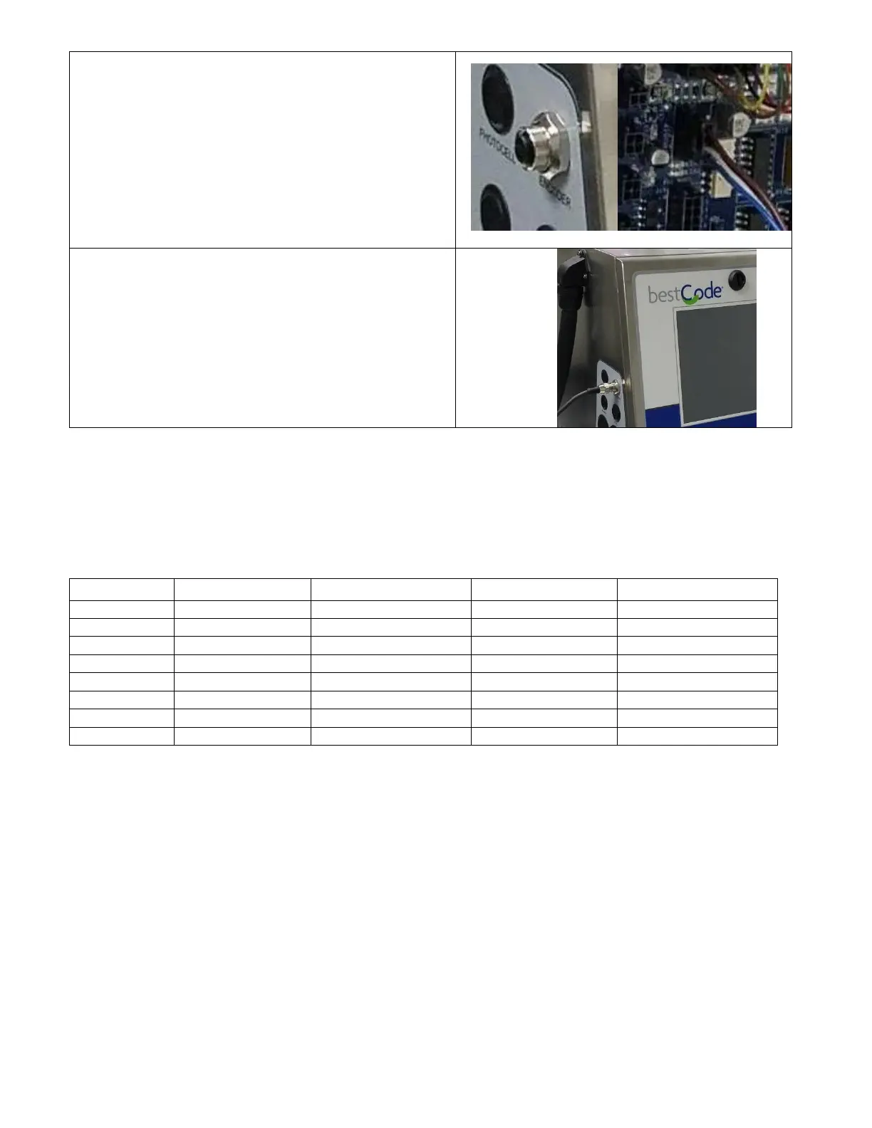
6. Install the Encoder cable.
7. Plug the Encoder cable into J15 on the board.
8. Lock the Electronic Compartment Door.
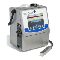
9. Install the M12 cable on the Encoder cable.
Wiring information
The peripheral devices for the Series 8 BestCode system use an array of connectors. For the Shaft Encoder,
Parallel, Photocell, and Auxiliary, Molex Microfit 3.0 connectors and crimps are used.
Name
Crimp
Housing
Tool
Cable
Alarm
Molex 43030-0008
Molex 43025-0600
Molex 63819-0000
22 AWG Suggested
Shaft Encoder
Molex 43030-0008
Molex 43645-0400
Molex 63819-0000
22 AWG Suggested
Parallel*
Molex 43030-0008
Molex 43025-1800
Molex 63819-0000
22 AWG Suggested
Ethernet
XXX
XXX
XXX
CAT5 Patch
Photocell
Molex 43030-0008
Molex 43025-0400
Molex 63819-0000
22 AWG Suggested
Auxiliary
Molex 43030-0008
Molex 43025-0400
Molex 63819-0000
22 AWG Suggested
Serial
XXX
XXX
XXX
DB9 Cable
USB
XXX
XXX
XXX
USB 2.0 or Higher
*Parallel cable kit is available. Kit interfaces with Series 8 Bulkhead wall to maintain IP Rating.
Notes:
1) Hand wiring and routing of foreign Peripherals may cause lapse in IP Rating.
a. To ensure IP Rating, use only BestCode supplied Peripherals.

Table of Contents

Related product manuals