U/T1 V/T2 W/T3
PE
L1 L2 L3
L1
L2
L3
1 2 5 6 13A13B13C 1 4 30 1 6 1 725 4 1 1
1 2 5 6 13A13B13C 1 4 30 1 6 1 725 4 1 1
SCAM E
SCAM E
M
R F
RUN
STOP
AUTO FWD
REV
U/T1 V/T2 W/T3
PE
L1 L2 L3
L1
L2
L3
1 2 5 6 13A13B13C 1 4 30 1 6 1 725 4 1 1
1 2 5 6 13A13B13C 1 4 30 1 6 1 725 4 1 1
SCAM E
SCAM E
M
R F
RUN
STOP
AUTO FWD
REV
WAR NING
DO NOT USE THIS
DISCONNE CT TO
STAR T ANDS TOP THE
FAN. PER MANENT
DAMAGE WIL L
RES ULT!
WAR NING
DO NOT USE THIS
DISCONNE CT TO
STAR T ANDS TOP THE
FAN. PER MANENT
DAMAGE WIL L
RES ULT!
WWW.BIGASSSOLUTIONS.COM © 2016 DELTA T CORP. ALL RIGHTS RESERVED.
23
10. Mount the Variable Frequency Drive (VFD)
WARNING: To reduce the risk of electric shock, wiring should be performed by a qualified electrician!
Incorrect assembly can cause electric shock or damage the motor and the controller! Hazard of electrical
shock!
WARNING: The installation of a Big Ass Fan must be in accordance with the requirements specified in this
installation manual and with any additional requirements set forth by the National Electric Code (NEC),
ANSI/NFPA, and all local codes. Code compliance is ultimately YOUR responsibility!
ATTENTION
If you are mounting the VFD to the fan motor frame instead of the wall (onboard VFD option), skip this step
and refer to the instructions that are packaged with the wall controller.
A. Select a Mounting Location
Adhere to the following guidelines when selecting the VFD location:
• Install the controller on a flat surface that is readily accessible, free from vibration, and where there is adequate
distance from foreign objects or moving equipment.
• Do not mount any controller adjacent to or above a heat source or heat-producing equipment.
• The ambient temperature must be between 14° F (-10° C) and 122° F (50° C) with a relative humidity range of 0 to
95% non-condensing.
• Do not expose the controller to a corrosive atmosphere or direct sunlight.
• When mounting the controller, keep in mind that the fan should be visible from the controller.
• A minimum distance of 6” (15.2 cm) should be maintained between controllers.
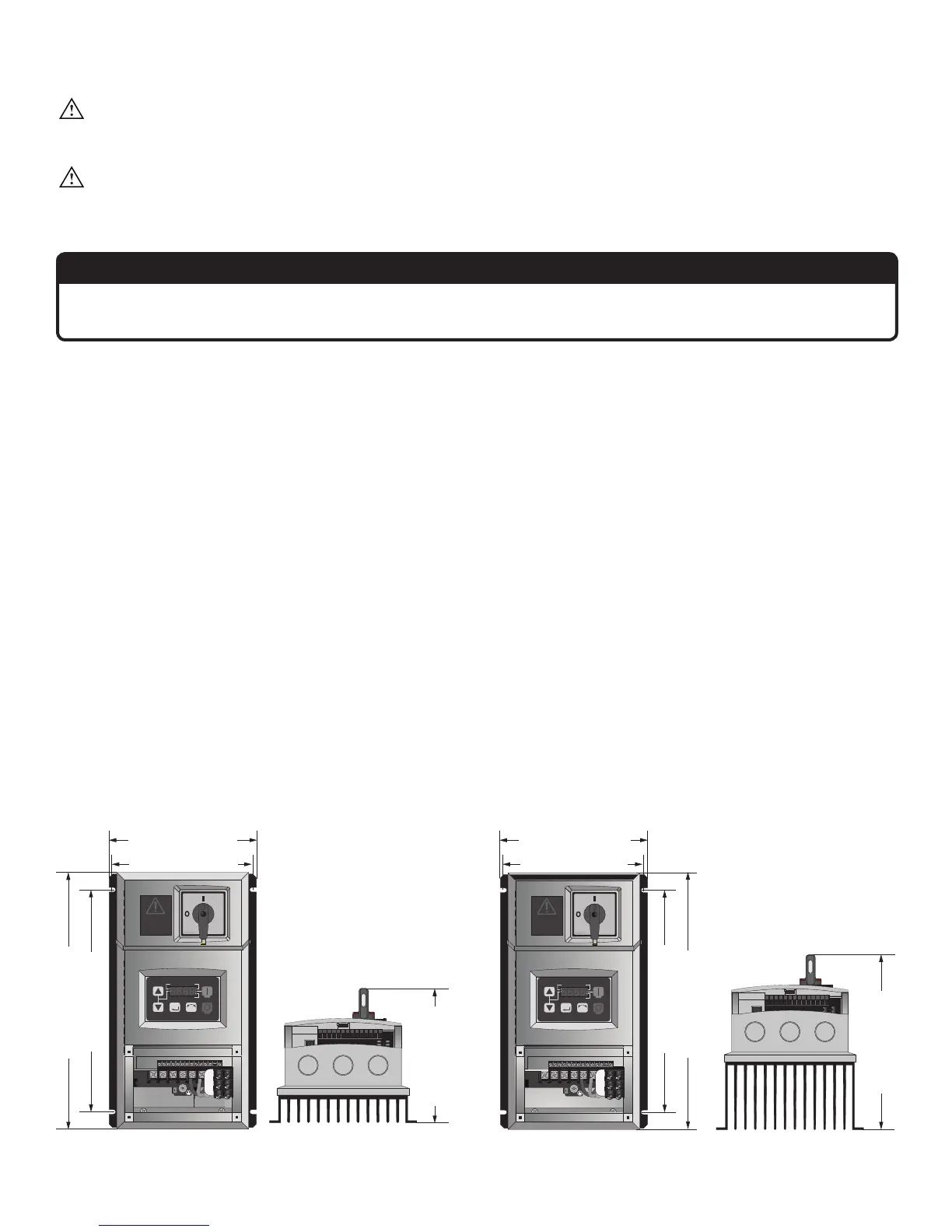
B. Mount the VFD
If the controller has been in storage or disconnected from power for more than one year, apply AC supply power
to the controller for a period of two hours prior to operation in order to recondition the internal DC bus capacitors.
Mount the VFD to the wall using a #8–#10 screw. Refer to the diagrams below for mounting hole dimensions.
2 hp Controller
1 hp Controller
6.25” (159 mm)
6.25” (159 mm)
5.95” (151 mm)
5.95” (151 mm)
10.9” (277 mm)
10.9” (277 mm)
9.5” (241 mm)
9.5” (241 mm)
5.51” (140 mm)
7.3” (185 mm)