U/T1 V/T2 W/T3
PE
L1 L2 L3
1 2 5 6 13A 13B 13C 14 30 16 1725 4 11
1 2 5 6 13A 13B 13C 14 30 16 1725 4 11
U/T1 V/T2 W/T3
PE
L1 L2 L3
1 2 5 6 13A 13B 13C 14 30 16 1725 4 11
1 2 5 6 13A 13B 13C 14 30 1 6 1725 4 11
WWW.BIGASSSOLUTIONS.COM © 2016 DELTA T CORP. ALL RIGHTS RESERVED.
35
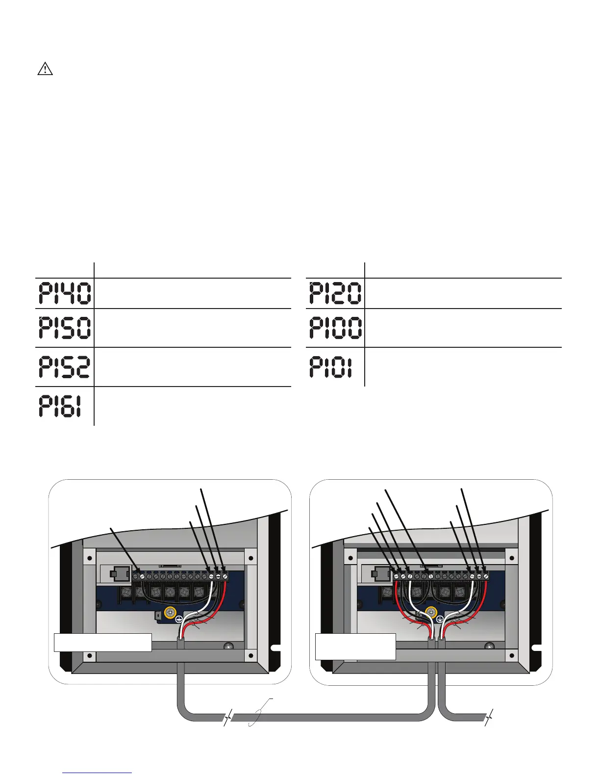
Daisy Chaining the Fans
WARNING: Wait three minutes after disconnecting before servicing!
The following illustrations and parameter changes enable daisy chaining of multiple fans. The first fan provides
a start/stop contact and 0–10 VDC analog speed reference for the first downstream VFD, which then provides a
new start/stop contact and 0–10 VDC analog speed reference for the following downstream VFD. This preferred
method of linking the VFDs together ensures minimal signal loss of command signals in larger multi-fan systems.
Assertion Level Switch (ALSW)
The VFD ships with the onboard digital I/O configured for Sourcing (PNP) operation. Terminal 4 provides +15
VDC to be used as a supply voltage for user-supplied switches and accessories. For this 3-wire daisy chaining
application, the downstream VFDs must be switched to Sinking (NPN) operation. Terminal 4 will then provide a DC
common connection and allow the analog signal and start/stop signal to share that common. The Assertion Level
switch above terminal 4 must be switched from (+) to (-) on all downstream VFDs for proper daisy chaining
operation prior to powerup, parameter changes, and operation.
Parameter changes (for first controller) Parameter changes (for downstream VFDs)
Parameter Description Parameter Description
Relay Output Function
Change from “0” for None to “1” for Run.
Assertion Level
Change from “2” for High to “1” for Low
TB-30 Output
Change from “0” for None to “1” for 0–10 VDC
output (scaled to drive output frequency).
Start Control Source
Change from “0” for keypad operation to “1”
for Terminal Strip.
TB-30 Scaling Frequency
Change to equal the frequency setting of
P103 Maximum Frequency.
Standard Reference Source
Change from “0” for keypad operation to “1”
for 0–10VDC analog input operation.
Speed at Max Signal
Change to equal the frequency setting of
P103 Maximum Frequency.
Note: Depending on the AWG and distance of the low voltage wiring, the downstream fans may run slightly slower than the leading fan.
If this occurs, P161 Speed at Max Signal can be used to introduce a minor command reference overshoot to compensate for the analog
voltage drop. At each downstream fan (beginning with the first), adjust the value of P161 up 0.1–0.2 Hz increments until the fan’s output
frequency matches that of the lead fan.
#17 = N.O. Relay Output
#17 = N.O. Relay Output
#16 = N.O. Relay Output
#16 = N.O. Relay
Output
#2 = Analog Common
3 conductor shielded cable minimum 20 AWG
Stranded (installer-supplied) Recommended
Maximum distance = 200 ft
#30 = 0–10 VDC Output
#30 = 0–10 VDC
Output
#4 = Digital Common*
0–10 VDC and Start/
Stop out to next
downstream controller
#2 = Analog Common
Terminals 2 and 16 shall be
tied together on the first VFD.
#1 = Run/Stop Input
#5 = 0–10VDC Input
Terminals 2, 4, and 16
shall all be tied together
on all downstream VFDs.
RED RED
RED
BLK BLK
BLK
WHT WHT
WHT