U
/T1
V
/T2
W
/T3
PE
L1 L2 L3
1 2 5 6 13A13B13C 14 30 16 1725 4 11
1 2 5 6 13A13B13C 14 30 16 1725 4 11
L1
L2
L3
U
/T1
V
/T2
W
/T3
PE
L1 L2 L3
1 2 5 6 13A13B13C 14 30 16 1725 4 11
1 2 5 6 13A13B13C 14 30 16 1725 4 11
L1
L2
L3
WWW.BIGASSSOLUTIONS.COM © 2016 DELTA T CORP. ALL RIGHTS RESERVED.
34
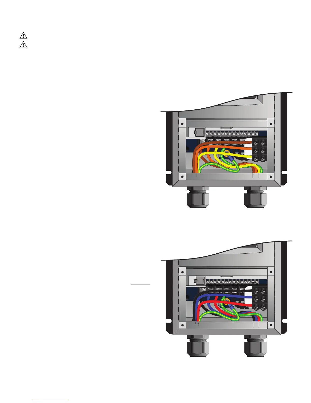
VFD Wiring: 400–480 V & 575–600 V, 3 Ф Controller
WARNING: Wait three minutes after disconnecting before servicing!
WARNING: Improper installation can cause electric shock or damage to the motor and controller. A
qualified electrician should perform the installation.
The diagrams below shows wiring options for a 400–480 V and 575–600 V, three-phase VFD. Note: The VFD
does not contain fusing! Power must be supplied to this controller via a dedicated circuit breaker or properly
fused disconnect!
400–480 V, 3 Φ, 50/60 Hz Controllers
An EMI filter and disconnect are included with the VFD
for 400–480 V, 3 Φ.
575–600 V, 3 Φ, 50/60 Hz Controllers
(Optional)
A disconnect is included with controllers for 575–600 V,
3 Φ. An EMI filter is not included with this VFD.
Note: When installing Powerfoil
®
8 fans in Canada,
customers with 600 VAC distribution must consider
one of two options to avoid damage to the motor:
1. Use the Onboard VFD kit, or
2. Utilize 200–240 VAC rated fans and controllers on their low
voltage power distribution (if they have room for the additional
circuits).
The motors used for Powerfoil8 fans are rated per NEMA
MG1 standards, which states that the motor insulation
must withstand 1,600 V PEAK–PEAK. 575–600 VAC
applications will exceed the safe voltage level of the
motor insulation system, resulting in a motor insulation
breakdown and subsequent motor failure.
AC Input Wiring
3W plus GND
Motor Output Wiring
3W plus GND
AC Input Wiring
3W plus GND
Motor Output Wiring
3W plus GND
BRN
BRN
ORG
ORG GRN/
YEL
GRN/
YEL
YEL
BLK
RED
GRN/
YEL
BLK
RED GRN/
YEL
BLU
BLU