a
b
WWW.BIGASSSOLUTIONS.COM © 2016 DELTA T CORP. ALL RIGHTS RESERVED.
39
ONBOARD VARIABLE FREQUENCY DRIVE
ATTENTION
It is the responsibility of the installer to install the fan according to facility and owner standards and all
local and national safety codes. Big Ass Fans does not provide additional means of disconnect when the
VFD is mounted onboard the fan. If preferred or required by local or national code, additional means of
disconnect should be provided by the installer as specified by the owner of the fan or facility manager.
Make sure to route the power wiring to the fan location before installing the VFD!
WARNING: Before servicing the fan, ensure power is disconnected.
Parts and hardware
If you are missing any parts or hardware, contact Customer Service. Note: The illustrations below are not to scale.
Wall Controller Mounting
Plate & Cover
(2) VFD Mounting
Bracket
VFD Interface
Module
1
(2) 1/4”-20 x 1.75”
Flange Head Bolt
(2) 1/4”-20
Flange Locknut
(4) 10-24 Pan
Head Screw
(2) 6-32 x 1.25” Flat
Head Screw
(4) 6-32 x 0.38” Flat
Head Screw
(4) 10-24 Nylock Nut
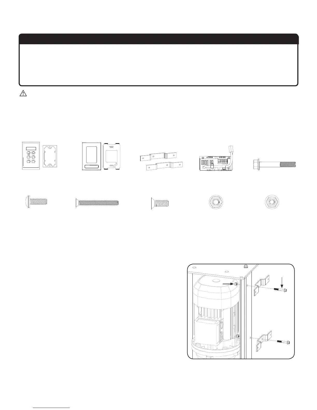
1. Attach mounting brackets
Attach the VFD mounting brackets using the Mounting Bracket
Hardware. Do not fully tighten the nuts.
Mounting Bracket Hardware:
a. (2) 1/4”-20 x 1.75” Flange Head Bolt
b. (2) 1/4”-20 Flange Locknut
1. The VFD interface module required for this installation is marked “RK” for Remote Keypad. A nearly identical module is used for BAFWorks
®
and Dewtect
®
installations. This
module is marked “RO” and is not compatible with remote keypad installations.
Wall Controller &
Rubber Gasket