W1
T3
V1
T2
U1
T1
W5
T9
V5
T8
U5
T7
V2
T5
U2
T4
W1
T3
V1
T2
U1
T1
W5
T9
V5
T8
U5
T7
W2
T6
V2
T5
U2
T4
W2
T6
WWW.BIGASSSOLUTIONS.COM © 2016 DELTA T CORP. ALL RIGHTS RESERVED.
36
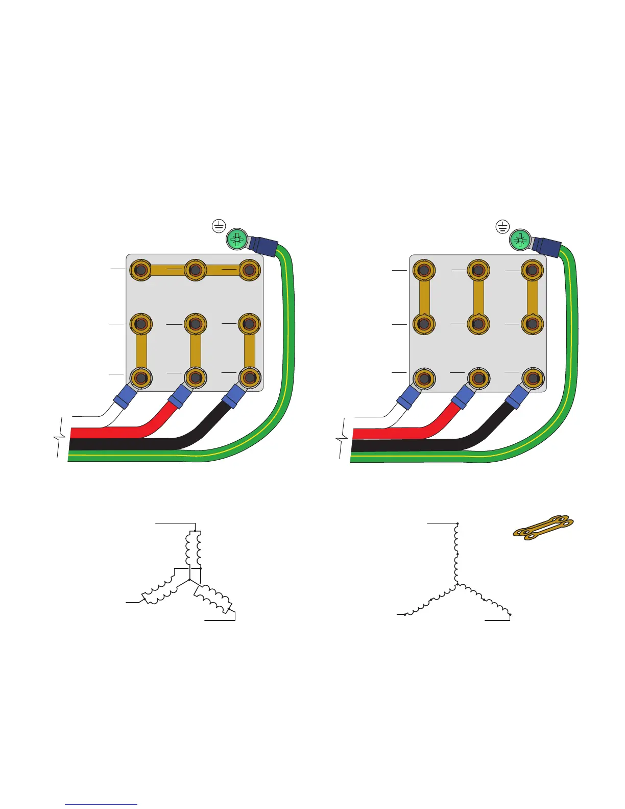
Motor Wiring: 9-Lead, Dual Voltage, Wye Motor Configurations
The motor wiring configurations shown below are applicable to 9-lead, dual voltage, wye wound motors rated for
230/460 VAC and 330/600 VAC. Consult the motor nameplate and/or wiring placard for verification of required
wiring connections. Motors with terminal blocks require ring terminals and a 7 mm nut driver for termination. The
diagrams below include L2 and L3 swap to yield proper motor rotation. Note: Swapping leads to reverse rotation
is done only on the output side of the drive.
Low Voltage
200–240 VAC, 50–60 Hz
330–350 VAC, 50–60 Hz
High Voltage
400–480 VAC, 50–60 Hz
575–600 VAC, 50–60 Hz
Jumper bars are
provided with the
motor
High Voltage
Low Voltage
GREEN W/ YELLOW TRACER
VAC from VFD
BLACK
GREEN W/ YELLOW TRACER
WHITE
RED
BLACK
WHITE
RED
VAC from VFD