SCA ME
SCA ME
WARNING
DO NOT USE THIS
DISC ONNECT TO
START A ND S TOP THE
FAN. PERMANE NT
DAMAG E WIL L
RE SUL T!
U
/T1
V
/T2
W
/T3
PE
L1 L2 L3
L1
L2
L3
SCA ME
SCA ME
M
R F
RUN
STOP
AUTO FWD
REV
WARNING
DO NOT USE THIS
DISC ONNECT TO
START AND STOP THE
FAN. PE RMANE NT
DAMAG E WILL
RE SUL T!
1 2 5 6 13A 13B 13C 1 4 30 1 6 1 725 4 11
1 2 5 6 13A 13B 13C 1 4 30 1 6 1 725 4 11
WWW.BIGASSSOLUTIONS.COM © 2016 DELTA T CORP. ALL RIGHTS RESERVED.
24
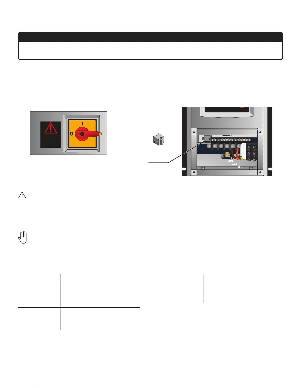
11. Install the Electronic Programming Module (EPM)
ATTENTION
If installing multiple fans, make sure to install the exact EPM included in each fan’s packaging. EPMs are
not interchangeable!
The Electronic Programming Module (EPM) contains all programming information specific to fan operation. It must
be installed prior to applying power to the VFD. This module is provided as part of the fan’s accessory kit.
To install the EPM, disconnect the fan from power (refer to the position of the disconnect switch below). Insert the
EPM in the location shown below. Note: The EPM can only be inserted one way. Do not force it!
12. Wire the Fan and VFD
WARNING: To reduce the risk of electric shock, wiring should be performed by a qualified electrician!
Incorrect assembly can cause electric shock or damage the motor and the controller!
Make sure power wiring is routed to the installation site. See Electrical Guidelines in the following section for
instructions and guidelines on wiring your fan.
If you are mounting the VFD to the fan motor frame instead of the wall (onboard VFD option), skip this step
and refer to the instructions at the end of this guide.
EPM
ORG
BRN
YEL
Disconnect Switch
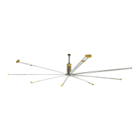
Powerfoil 8 Plus
Fan Diameter Minimum Supply Circuit Size
12–24 ft
(3.6–7.3 m)
25 A @ 200–240 V, 1 Φ
15 A @ 200–240 V, 3 Φ
10 A @ 400–480 V, 3 Φ
10 A @ 575–600 V, 3 Φ
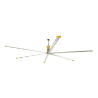
Basic 6 & Powerfoil
8
Fan Diameter Minimum Supply Circuit Size
8–10 ft
(2.4–3.0 m)
15 A @ 100–125 V, 1 Φ
15 A @ 200–240 V, 1 Φ
10 A @ 200–240 V, 3 Φ
10 A @ 400–480 V, 3 Φ
10 A @ 575–600 V, 3 Φ
12–24 ft
(3.6–7.3 m)
25 A @ 200–240 V, 1 Φ
15 A @ 200–240 V, 3 Φ
10 A @ 400–480 V, 3 Φ
10 A @ 575–600 V, 3 Φ