a
b
a
To Junction
Box (in Wall)
WWW.BIGASSSOLUTIONS.COM © 2016 DELTA T CORP. ALL RIGHTS RESERVED.
40
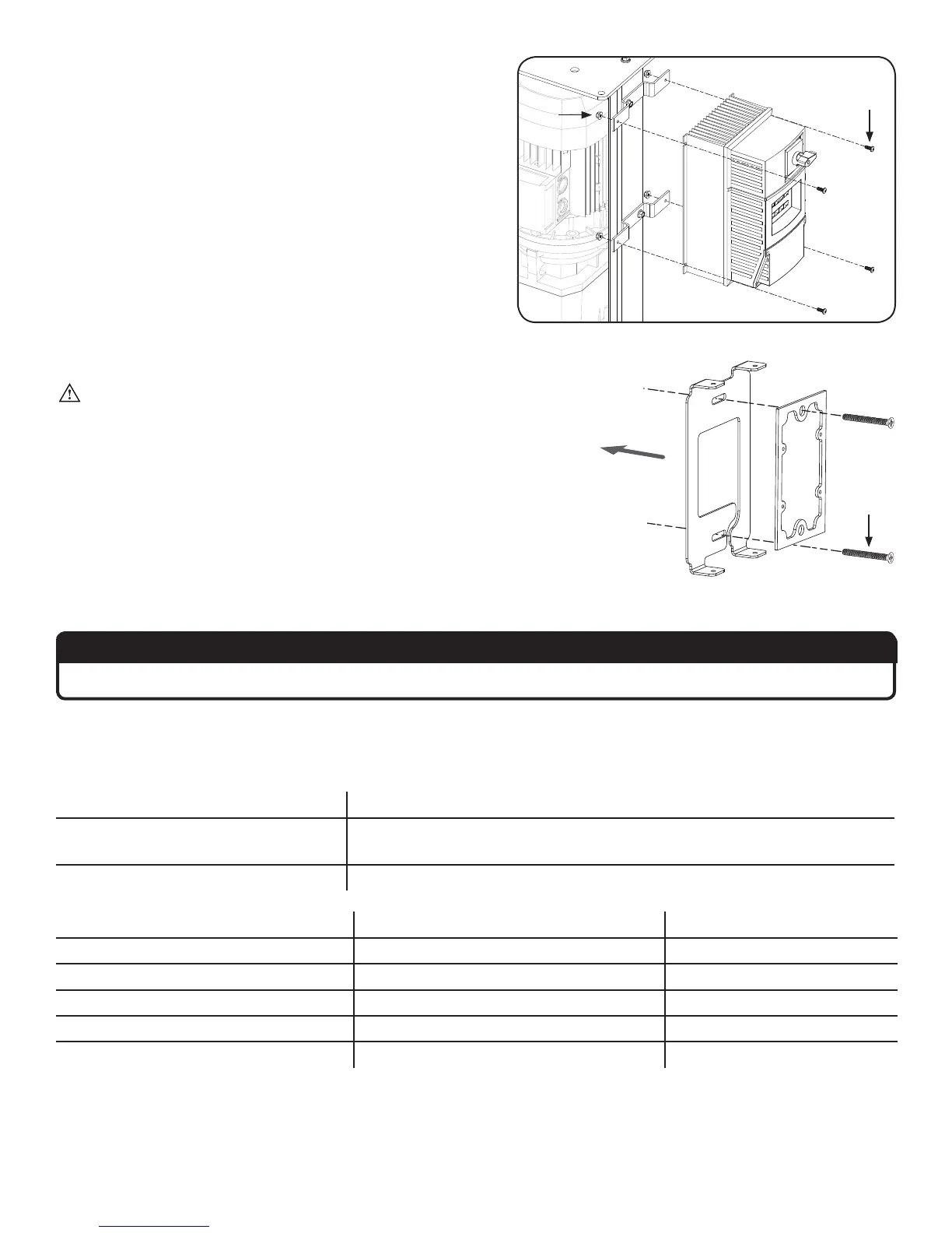
2. Attach VFD and tighten nuts
Secure the VFD (provided with the fan) to the mounting
brackets using the VFD Hardware. Fully tighten the 1/4”
locknuts from the previous step.
VFD Hardware:
a. (4) 10-24 Pan Head Screw
b. (4) 10-24 Nylock Nut
3. Attach mounting plate
WARNING: Ensure the VFD is disconnected from power.
Wait three minutes after disconnecting before servicing!
Select a mounting location that is visible from the fan. Remove the
two (2) screws and the rubber gasket from the back of the wall
controller. Discard the screws. Attach the rubber gasket and the
wall controller mounting plate to the junction box in the wall with
the 6-32 x 1.25” flat head screws (a). Note: The mounting plate fits
a standard junction box (not supplied).
4. Connect to VFD
ATTENTION
Steps a–g below MUST be completed in the order shown.
a. Make the electrical connections to the VFD as described in the Electrical Installation section.
b. Install the VFD interface module, and then wire the wall controller to the module. Refer to the table and the
illustration below for wiring instructions and the appropriate communications cable for your application.
Length of run (controller to VFD) Cable to use
≤ 100 ft (30.5 m)
Belden 8332, General Cable C0620, or equivalent with 300 V jacket
insulation
100 ft (30.5 m) < x ≤ 328 ft (100 m) 18–16 AWG 4 conductor shielded cable
VFD interface module terminal Description Wall controller terminal
1 Wall controller power (-) 2
2 Communication (TXA) TXA
3 No connection --
4 Communication (TXB) TXB
5 Wall controller power (+) 11