12345
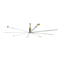
7mm
<
(16-26 AWG)
0.5 Nm/ 4.5 lb-in
6 mm
<
(16-26 AWG)
0.2 Nm/ 2 lb-in
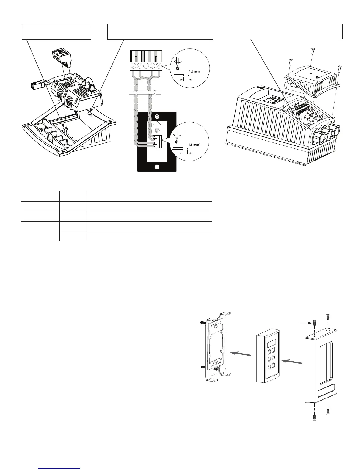
Mounting
Plate
Wall
Controller
Controller
Cover
a
WWW.BIGASSSOLUTIONS.COM © 2016 DELTA T CORP. ALL RIGHTS RESERVED.
41
c. For proper functionality, set the following VFD parameters in the order shown from the VFD’s main keypad:
Parameter Set to Description
P199 00 Unlock EPM to user programming
P100 02 Set start source to wall controller only
P400 01 Set network protocol to wall controller
P166 00 Set PWM frequency to 10 kHz
Note: The P166 setting should only be set to 00 on VFDs mounted to the fan frame as described in these
instructions. All other “long lead” installations should remain set to 01.
Note: A control configuration fault (“F_Fnr”) may be displayed after you change P100 or P400. You can ignore this
fault by pressing STOP on the main VFD keypad.
d. Power down the fan, and then insert a jumper wire between terminals 1 and 4 on the VFD terminal strip for a
drive RUN enable. Do not install the jumper before making the parameter changes listed in the previous step.
e. Secure the lower VFD cover with the four screws and
reapply AC power.
f. Rest the wall controller in the controller cover, and then
secure the cover to the mounting plate with the 6-32 x
0.38” flat head screws (a).
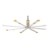
1. Install module under this
tab first.
2. Roll module into position under this tab.
Module will click into place.
3. Plug module’s 6-pin connector into the “PL3”
socket on the VFD.