U
/T1
V
/T2
W
/T3
PE
L1 L2 L3
1 2 5 6 13A13B13C 14 30 16 1725 4 11
1 2 5 6 13A13B13C 14 30 16 1725 4 11
L1
L2
L3
U
/T1
V
/T2
W
/T3
PE
L1 L2 L3
1 2 5 6 13A13B13C 14 30 16 1725 4 11
1 2 5 6 13A13B13C 14 30 16 1725 4 11
L1
L2
L3
WWW.BIGASSSOLUTIONS.COM © 2016 DELTA T CORP. ALL RIGHTS RESERVED.
33
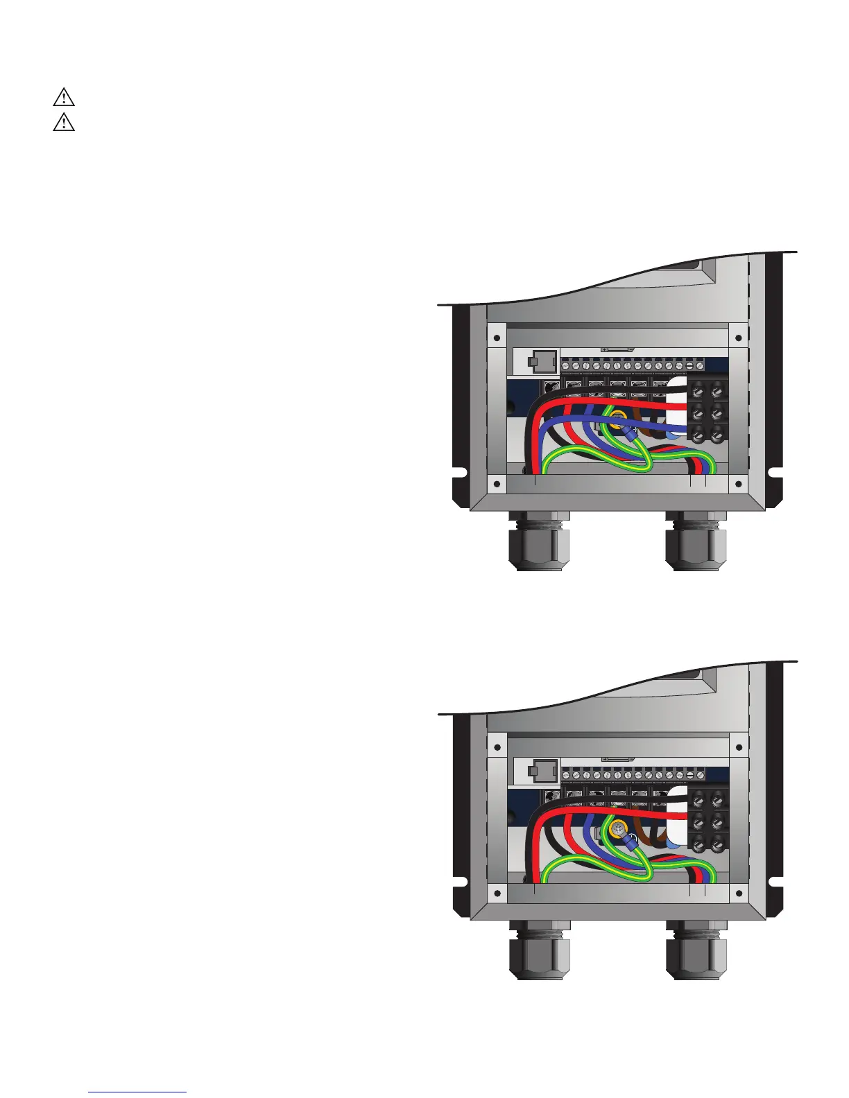
VFD Wiring: 200–240 V, 3 Ф Controller
WARNING: Wait three minutes after disconnecting before servicing!
WARNING: Improper installation can cause electric shock or damage to the motor and controller. A
qualified electrician should perform the installation.
The diagrams below shows wiring options for a 200–240 V, three-phase VFD. Note: The VFD does not contain
fusing! Power must be supplied to this controller via a dedicated circuit breaker or properly fused disconnect!
200–240 V, 3 Φ, 50/60 Hz Controllers
A disconnect is included with the VFD for 200–240 V,
3 Φ. An EMI filter is not included with this VFD.
Optional 1 Φ Wiring for 200–240 V, 3 Φ,
50/60 Hz Controllers
The L3 terminal is not used when wiring the VFD for
200–240 V, 1 Φ. A disconnect is included with the
VFD. An EMI filter is not included with this VFD.
AC Input Wiring
3W plus GND
Motor Output Wiring
3W plus GND
AC Input Wiring
2W plus GND
Motor Output Wiring
3W plus GND
BLK
RED
GRN/
YEL
BLK
RED GRN/
YEL
BLU
BLK
RED
GRN/
YEL
BLK
RED GRN/
YEL
BLU