24
Pressure Relief Valve Adjustment Flow Restrictor Valve Replacement
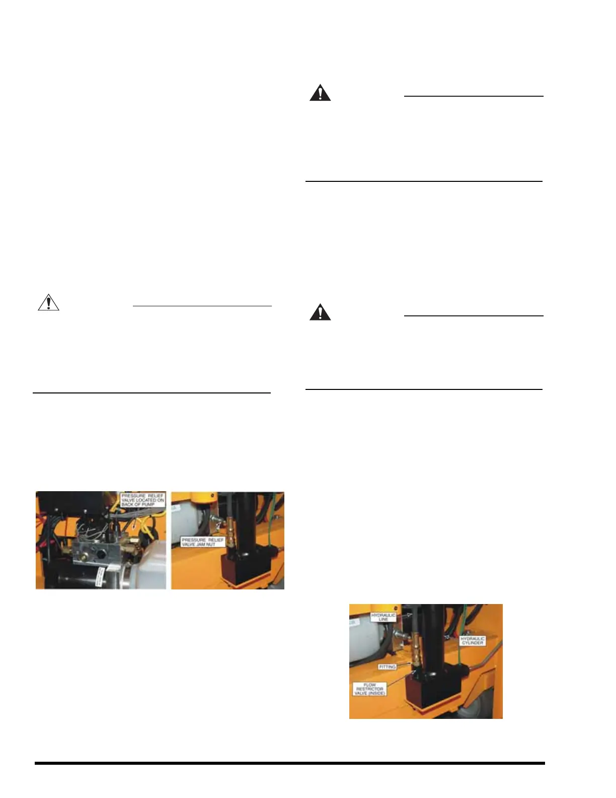
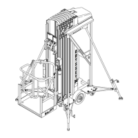
Perform the following procedure to adjust the
pressure relief valve. Refer to Figure 4-6.
Move the ESP 19 lift platform to the fully DOWN
position.
Center 450 pounds of weight on the lift platform.
Loosen the jam nut. The pressure relief valve is
on the back side of the pump.
Turn the pressure relief valve adjust screw 1/8
th
turn counterclockwise. This will adjust the relief
valve bypass pressure setting for less than 450
pounds of lift.
Place the key switch in the LOWER CONTROL
position and press the UP pushbutton. The
pump should run, bypassing oil to the hydraulic
reservoir.
CAUTION
Do not adjust the pressure relief valve for a
bypass pressure higher than needed to raise
the 450 pound load. Hydraulic system overload
may occur at a higher bypass pressure,
causing hydraulic failures or damage to the
equipment.
With the platform lift function enabled (pump
running), turn the pressure relief valve adjust
screw clockwise just enough to smoothly raise
the platform without bypassing oil to the
hydraulic reservoir.
Retighten the jam nut.
Figure 4-6. Pressure Relief Valve Adjustment
WARNING
Closely read and adhere to the following
instructions whenever you remove and install
the flow restrictor valve. Failure to properly
install the flow restrictor valve can result in
serious injury or death to personnel or damage
to the equipment.
The flow restrictor valve, Figure 4-7, is located inside
the base of the hydraulic lift cylinder. If the flow
restrictor valve needs to be removed or replaced, it
is important that it be properly reinstalled.
Raise the platform and masts high enough to
access the fitting. Support the raised platform
using a forklift or hoist to prevent it from
lowering.
WARNING
Never work under the lift while it is raised
unless the platform is fully supported to
prevent it from lowering. Failure to properly
support a raised platform can result in serious
crushing injury or death.
Remove the hydraulic line from the fitting. Then,
remove the fitting.
Remove the flow restrictor valve using a 3/16”
allen wrench.
When reinstalling the flow restrictor valve, make
sure it is tightened in all the way against the
bottom.
When reinstalling the fitting, do not tighten it
against the flow restrictor. If the fitting is turned
in too far, it can reduce or stop the oil flow to the
cylinder.
Finally, reconnect the hydraulic line to the fitting.
Make sure the o-ring seal on the face of the
fitting is not cut or torn.
Figure 4-7. Flow Restrictor Valve