VD (E2.1) 10/2011 page 20/83
When placing several units of the same size side by side, maintain a minimum distance of 250 mm / 9.8
in between each unit. Wall distances: rear 100 mm / 3.9 in, sides 135 mm / 5.3 in. Spacing above and
behind the unit of at least 100 mm / 3.9 in must also be maintained.
CAUTION
Danger by stacking.
Damage to the units.
∅ Do NOT place vacuum drying ovens on top of each other.
To completely separate the unit from the power supply, you must disconnect the power plug. Install the
unit in a way that the power plug is easily accessible and can be easily pulled in case of danger.
Do not install or operate the vacuum drying oven VD in potentially explosive areas.
DANGER
Explosion hazard.
Danger of death.
∅ Do NOT operate the unit in potentially explosive areas.
KEEP explosive dust or air-solvent mixtures AWAY from the vicinity of the unit.
For operation with inert gas, the unit is supplied with an oxygen-displacing gas, e.g. N
2
. The gas
emerging from the system must be removed from the installation area by means of a suitable extraction
system (see technical ventilation measures in the guideline BGI/GUV-I 850-0 on safe working in
laboratories (formerly BGR/GUV-R 120 or ZH 1/119 laboratory guidelines issued by the employers’
liability insurance association) (for Germany).
The maximum permissible ambient temperature of the vacuum pumps delivered by BINDER is 40 °C /
104°F.
4. Installation and connections
4.1 Vacuum expansion racks
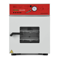
The low-loss heat transfer to the material occurs via the
patented aluminum vacuum expansion racks (also available in
stainless steel as an option). The strong tension causes the
racks to fit tightly against the interior wall and their large-
surface contact area ensures rapid and effective heat transfer.
The removable rack holders allow for easy positioning.
You can also remove the expansion racks for easy cleaning.
Do not remove them too often in order to prevent wear.
Figure 8: Using the expansion racks
• Pushing the locking lever: The expansion rack is released and can be removed.
• Pulling the locking lever: The expansion rack is pressed against the inner chamber walls.
Following each new tightening of an expansion rack, check that the lateral parts of the rack fit
closely over their whole surface to the inner chamber wall. This is necessary in order to
ensure the specified temperature exactitude.